
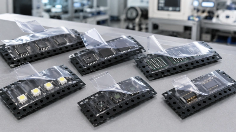
Selecting cover tape for electronic components is not a matter of assigning one adhesive system to each package name. An IC, QFN, BGA, LED, sensor, or connector may require a different validation approach because geometry, mass, pocket fit, surface sensitivity, carrier material, application equipment, and feeder conditions interact.
The objective is not to find the strongest cover tape. It is to identify a cover tape and carrier tape combination that keeps components secure during winding, storage, and transport, then opens smoothly during SMT feeding. Buyers who need a basic introduction can first review this SMT cover tape guide. For a real project, selection should begin with measurable packaging risks rather than the component family alone.
Start With the Component Risk Profile
A component family identifies likely risks, but it cannot determine the final cover tape. Two QFN packages may differ in dimensions, mass, exposed-pad structure, pocket clearance, and feeder conditions. Two LEDs may use different lens materials or have different sensitivity to contact, particles, and electrostatic charging.
Texas Instruments documentation for a specific QFN package shows that either heat-activated or pressure-sensitive cover tape may be used within a qualified tape-and-reel system. This demonstrates why “QFN equals one cover tape type” is not a reliable engineering rule. The component, carrier tape, application process, and feeding result must be evaluated together.
Before comparing materials, define five risk areas:
- Component dimensions, mass, and center of gravity.
- Sensitive surfaces, solder balls, leads, lenses, ports, or exposed contacts.
- Pocket clearance and possible rotation, tilt, or vertical movement.
- ESD, cleanliness, optical inspection, and contamination requirements.
- Application equipment, peel path, feeder model, and production speed.
This risk profile helps a supplier shortlist suitable options, but it does not replace testing on the actual packaging system.
Prepare the Selection Inputs Before Requesting Samples
Provide the component drawing, dimensions, height, mass, orientation, and details of any sensitive surface. For sensors and LEDs, identify optical windows, lenses, membranes, ports, coatings, or areas that must not contact the cover tape. For BGA devices, explain how the pocket supports the package while protecting the solder-ball area.
Carrier tape information is equally important. Provide the material, width, pocket dimensions, pocket depth, seal-flange condition, and drawing revision. Flange width, flatness, contamination, and forming variation can directly affect adhesion and peel consistency.
Cover tape width must match the available sealing area, not simply the nominal carrier tape category. Use this cover tape width matching guide when preparing the drawing.
Also document the application method, machine model, available process controls, line speed, reel format, feeder model, and known peel path. For an existing failure, send affected reels, lot labels, defect photographs, peel curves, and a slow-motion feeder video. These inputs allow the supplier to distinguish a cover tape issue from a pocket-fit, carrier-flatness, process-control, or feeder problem.
Selection Priorities by Component Type
ICs: Orientation, ESD Risk, and Package Variation
“IC” includes SOIC, TSSOP, DFN, LGA, and many other structures. Begin with the package drawing rather than a general semiconductor label.
For thin or lightweight ICs, excessive vertical or lateral clearance can allow rotation when the cover tape is peeled. For leaded packages, the pocket should support the body without stressing terminals. Pin 1 orientation must remain stable through winding, transport, and feeding.
ESD protection also requires a system review. An anti-static or conductive carrier tape alone does not prove that the complete package is suitable for an electrostatic-sensitive device. Cover tape surfaces, the reel, handling environment, grounding, and customer requirements also matter.
When the carrier has not been finalized, review carrier tape selection for IC packaging before approving the cover tape.
QFN: Low Profile and Peel-Induced Movement
QFN packages are often low profile, making package height, pocket depth, and top clearance important. Excessive space can allow lift or rotation; insufficient clearance can create contact with the cover tape.
Observe the QFN at the feeder peel point. A stable average peel value is not enough if short force spikes make the carrier vibrate or the component jump. Review the full curve, verify orientation before and after peeling, and inspect samples from several reel positions.
Do not state that QFN always requires heat-activated or pressure-sensitive cover tape. Either system may be considered when the complete package and process are qualified.
BGA: Solder-Ball Protection and Clean Release
The pocket should support the BGA body while protecting solder balls from friction, compression, and repeated movement. Review package mass, height, winding curvature, and possible tilt.
A heavier component does not automatically require higher peel force. Excessive or unstable resistance may transmit more disturbance into the carrier. The target is a continuous seal, repeatable peel profile, no adhesive transfer, and reliable feeder release.
Inspect pocket support, top clearance, solder-ball condition, particles, residue, component movement, and pick-up performance after relevant storage or transport testing.
LEDs: Lightweight Parts, Optical Surfaces, and Sticking
Small LEDs can be sensitive to peel disturbance because they are lightweight and may have optical surfaces that must remain clean. The lens or phosphor surface should not rub against the cover tape, and the pocket should control rotation so polarity remains correct.
Sticking may involve more than adhesive residue. Triboelectric charging, grounding, ionization, component-to-cover clearance, and feeder geometry may contribute. A Vishay application note on ChipLED sticking discusses electrostatic and mechanical factors, showing why actual packaging and handling conditions must be investigated.
Use real LEDs, the intended carrier, the target feeder, and slow-motion observation. For pocket-design considerations, see carrier tape for LED packaging.
Sensors: Sensitive Ports, Membranes, and Windows
A molded QFN-style sensor, optical sensor, pressure sensor, and device with an exposed port may need different controls.
Identify every surface that must remain unobstructed and free from particles, haze, or adhesive transfer. Confirm orientation and whether the sensitive area faces upward. The pocket should prevent rotation while keeping ports, membranes, and optical windows away from the cover tape.
Moisture-sensitive handling is a separate decision. Cover tape closes carrier pockets for transport and feeding, but it should not automatically be described as moisture-barrier packaging. When required, dry packing, moisture-barrier bags, desiccant, and humidity indication must be assessed separately.
Connectors: Height, Mass, and Contact Protection
Connectors may have tall, heavy, or asymmetrical geometries. Housings, latches, pins, solder tails, and exposed contacts create multiple contact risks. The pocket should control the center of gravity without loading fragile terminals.
Check component height, pocket depth, cover clearance, and reel winding. For asymmetrical parts, verify orientation across the reel. A short laboratory strip may appear stable while a full reel exposes curvature, tracking, or side-clearance problems.
Physical samples are especially important because drawings may not fully describe flexibility, sharp edges, protruding contacts, or how the component settles.
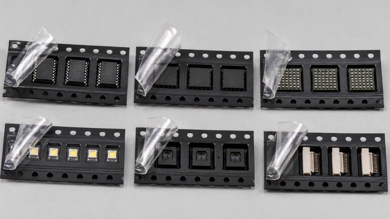
Choose the Adhesive System by Process Capability
A heat-activated adhesive cover tape forms its seal through controlled heat, pressure, and contact time. The process window depends on the cover tape, carrier material, sealing-head geometry, dwell time, pressure distribution, and equipment calibration. Supplier data may provide starting conditions, but it applies only to the named product and stated test setup.
Where the line has suitable thermal control, evaluate heat-activated cover tape with the actual carrier. Examine seal-band continuity, carrier deformation, peel profile, edge lifting, wrinkles, and post-storage performance.
Pressure-sensitive adhesive cover tape bonds mainly through controlled pressure and normally does not require heat to activate the adhesive. It can be considered where thermal exposure is undesirable or heat-sealing equipment is unavailable. However, clean sealing lanes, alignment, roller contact, stable pressure, and carrier compatibility still require control.
For this process route, review pressure-sensitive cover tape and qualify it under the intended application and feeder conditions.
Neither adhesive system should be selected by package name alone. The better option is the one that can be applied consistently on the customer’s equipment and can pass the agreed package, peel, cleanliness, and feeding tests.
Use a Component Application Matrix
| Component family | Priority risk | Cover tape review | Required validation |
|---|---|---|---|
| ICs | Orientation, ESD, and lead protection | Surface properties and peel consistency | Pocket fit, ESD review, and feeder trial |
| QFN | Low profile, rotation, and movement | Stable peel and clean release | Peel observation and orientation check |
| BGA | Ball protection, mass, and tilt | Residue control and repeatable opening | Ball inspection and feeder trial |
| LEDs | Sticking, jumping, and optical surfaces | Static behavior and cleanliness | Slow-motion peel and lens inspection |
| Sensors | Sensitive ports, membranes, or windows | Particle, haze, and residue risk | Orientation and cleanliness inspection |
| Connectors | Height, center of gravity, and contacts | Secure seal without excessive disturbance | Full-reel winding and feeder test |
The matrix identifies what to test; it does not provide a universal material assignment. Similar packages may require different solutions, while one component family may qualify more than one cover tape system.
Validate the Actual Tape-and-Reel Combination
Begin with alignment and seal-band inspection. Look for uneven lanes, wrinkles, bubbles, channels, edge lifting, carrier deformation, and contamination. Increasing heat or pressure may hide a mismatch temporarily while increasing deformation or peel variation. The carrier tape and cover tape compatibility guide explains why the interface must be evaluated as a material system.
Peel records should identify the cover tape, carrier tape, lots, conditioning, application settings, peel angle, peel speed, equipment, sample width, direction, and whether the specimen is initial, aged, or post-storage. One average without conditions is not enough.
When EIA-481 is referenced, distinguish an applicable standard requirement from a supplier’s internal control range and the customer’s acceptance criteria. Jiushuo’s EIA-481 tape-and-reel requirements guide provides an overview, but the applicable standard version and customer specification should control the qualification plan.
Review the full peel curve for spikes and variation, then observe component jump, rotation, delayed release, sticking, particles, scratches, and residue at the feeder. See cover tape peel force and SMT feeding stability for a deeper explanation.
Complete trials at the intended feeder speed, including start-stop cycles and multiple reel positions. Where storage, aging, humidity, or transport may affect performance, define appropriate conditioning and retesting from the approved specification and customer requirements.

Information to Send for a Technical Recommendation
Send the following before requesting a final recommendation:
- Component part number, drawing, dimensions, mass, and orientation.
- Details of lenses, ports, membranes, balls, leads, or exposed contacts.
- ESD, optical inspection, cleanliness, and customer requirements.
- Carrier material, width, drawing, pocket dimensions, and physical samples.
- Existing cover tape and current application settings.
- Equipment, line speed, reel format, and feeder model.
- Defect photographs, peel data, lot labels, and feeder video.
- Forecast volume and sample or production schedule.
Jiushuo can review these inputs as a complete packaging system and help define a sample-validation plan. Buyers can compare cover tape options for tape-and-reel applications before submitting drawings and samples.
For tall connectors, irregular sensors, or LEDs with sensitive optical surfaces, physical samples may be necessary because drawings do not always show how the component settles, moves, or reacts at the peel point.
Qualify the System Before Mass Production
Final approval should cover engineering samples, a pilot run, and document control. Confirm component fit, seal appearance, peel consistency, residue, ESD or cleanliness requirements, feeder performance, winding, and post-storage behavior. Record the approved material combination and process conditions by lot.
Requalification may be needed when the component package, pocket drawing, carrier material, cover tape construction, application equipment, feeder, storage condition, or customer specification changes.
Cover tape selection is most reliable when the component, pocket, carrier material, adhesive system, process, reel, and feeder are treated as one system. Send Jiushuo your component drawing, carrier tape specification, equipment information, and current packaging issue to request a component-specific review before mass production.
FAQ
Is heat-activated cover tape always better for QFN or BGA packages?
No. Package type alone cannot determine the adhesive system. The carrier material, pocket fit, application equipment, peel behavior, component movement, and feeder performance must be tested together.
Can the same cover tape be used for ICs, LEDs, and sensors?
It may be possible, but each combination still requires validation. These components can differ in weight, top-surface sensitivity, ESD requirements, cleanliness limits, and pocket behavior.
What information is required before selecting cover tape?
Provide the component drawing, dimensions, mass, orientation, sensitive-surface details, carrier tape material and drawing, application method, equipment, feeder information, and any existing defect evidence.
How should lightweight LEDs be checked for sticking or jumping?
Use the intended carrier tape and feeder, observe the peel point, review pocket clearance, verify grounding and electrostatic controls, and inspect the LED lens or optical surface after peeling.
Does anti-static carrier tape remove the need to evaluate the cover tape?
No. ESD performance must be evaluated across the full packaging and handling system, including the cover tape, carrier tape, reel, environment, grounding, and customer requirements.
Does cover tape provide moisture-barrier protection for MSL components?
Cover tape closes carrier pockets for transport and feeding, but it should not automatically be treated as moisture-barrier packaging. Dry packing, moisture-barrier bags, desiccant, and humidity indicators may still be required.
When should cover tape qualification be repeated?
Requalification should be considered after changes to the component package, carrier material, pocket drawing, cover tape construction, application equipment, feeder, storage conditions, or customer specification.