
Precision Carrier Tape Packaging Solutions from China

Heat Activated Cover Tape for SMT Automated Packaging

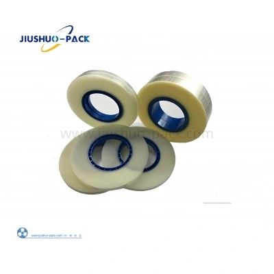
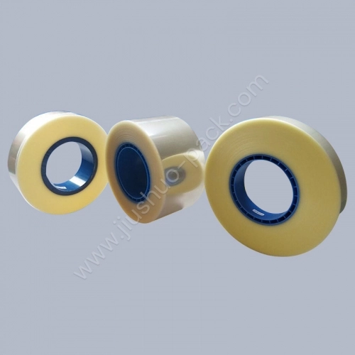
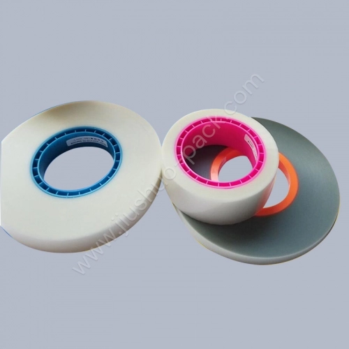
Heat-Activated Cover Tape is designed for continuous SMT taping operations that use controlled heat and pressure to bond the sealing layer to compatible embossed carrier tape.

During the sealing process, a heated sealing head or roller activates the adhesive layer, while controlled pressure and dwell time create uniform seal bands along both carrier tape flanges. Proper adjustment of temperature, pressure, contact time, and line speed is essential for maintaining consistent seal integrity and peel performance.

This cover tape is suitable for automated, inline tape-and-reel packaging environments where sealing stability, width alignment, and repeatable peel force are critical to downstream pick-and-place performance.

It is intended for integration with compatible embossed carrier tapes in reel-to-reel processes that require reliable component retention, controlled sealing, and stable SMT feeding.

    Production Environment Suitability

  • Heat-and-pressure continuous sealing lines
  • High-speed SMT taping machines with heated sealing heads or rollers
  • Inline taping systems with adjustable temperature and pressure controls
  • Automated reel-to-reel tape-and-reel packaging workflows
  • Applications requiring consistent seal strength and controlled peel force
  • Long production runs with monitored sealing parameters
  • Share:

Sealing Structure & Working Principle

  • Sealing Structure

    Heat Activated Cover Tape features a multi-layer film structure with a heat-activated adhesive sealing layer designed for continuous taping systems. The sealing layer remains stable during handling and forms a uniform bond when controlled heat and pressure are applied at the carrier tape flanges.

    The structure supports consistent sealing performance across long reel-to-reel production runs.

    Working Principle

    Sealing is achieved by applying controlled heat and pressure at the sealing station. The heated sealing head or roller activates the adhesive layer, while pressure and dwell time create repeatable seal lines along both carrier tape flanges.

    The sealed interface delivers stable, predictable peel behavior at standard SMT feeder peel angles, supporting reliable downstream feeding.
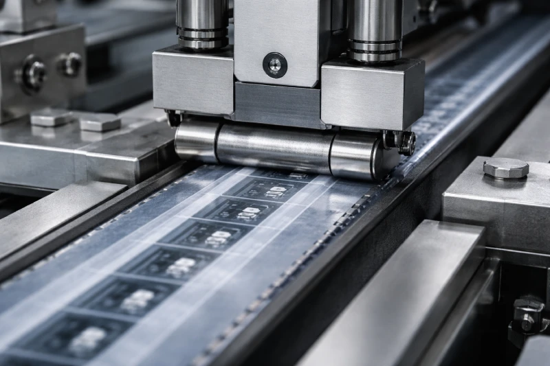
  • Heat activated cover tape sealing structure showing heat-and-pressure bonding to embossed carrier tape during continuous SMT reel-to-reel packaging

Anti-Static Configuration & Model Classification

Heat Activated Cover Tape is available in anti-static configurations to support stable handling of ESD-sensitive components during taping, storage, transport, and feeder use. The anti-static layer is engineered to reduce charge accumulation on the cover tape surface while maintaining the intended heat-and-pressure sealing performance.

Configuration Logic

  • Single-sided anti-static: anti-static performance on the outer surface for handling and line contact control

  • Double-sided anti-static: anti-static on both sides for applications requiring controlled charge behavior across the full tape interface

Model Classification (Heat Activated)

  • JSLF-06D — Single-sided anti-static heat activated cover tape

  • JSLF-06S — Double-sided anti-static heat activated cover tape

What to Confirm Before Selection

  • Component ESD sensitivity level and handling requirement

  • Required anti-static coverage (single vs double side)

  • Reel length preference aligned with line changeover frequency

  • Target peel behavior stability at feeder-level operation

Models shown below focus on anti-static configurations for heat-and-pressure continuous sealing lines.

Product Model Type Cover Tape ESD Thickness Length
Heat Activated Cover Tape JSLF-06D Single-sided anti-static cover tape ESD anti-static 10^7–10^9 58 ± 5 μm 200 m/roll, 400 m/roll, 500 m/roll
Heat Activated Cover Tape JSLF-06S Double-sided anti-static cover tape ESD anti-static 10^7–10^9 58 ± 5 μm 200 m/roll, 400 m/roll, 500 m/roll

Carrier Tape Compatibility & Width Matching

For stable production, cover tape width should be selected according to the nominal carrier tape width. The tape must contact both sealing flanges evenly while remaining clear of the sprocket holes and component pocket opening.

  • Compatibility Focus

    • Compatible with standard embossed carrier tapes used in SMT automated packaging

    • Sealing performance depends on flange geometry, tape flatness, and width tolerance control

    • Width mismatch can lead to edge lifting, inconsistent seal bands, or unstable peel behavior at feeder level

  • Width Matching Rule

    • Select cover tape width based on carrier tape width specification

    • Confirm final width with actual carrier tape samples when flange structure or material differs from standard

Width Matching Select the recommended cover tape width for the nominal carrier tape width to maintain centered, continuous seal bands on both flanges.

Specification 8 12 16 24 32 44 56 72 88
Carrier tape width (mm) 8 12 16 24 32 44 56 72 88
Cover tape width (mm) 5.3 9.3 13.3 21.3 25.5 37.5 49.5 65.5 81.5

Suitable SMT Automation Scenarios

Heat Activated Cover Tape is suited for SMT taping environments where continuous operation, sealing stability, and feeder-level consistency are prioritized over flexible manual adjustment. It is typically applied in automated lines where sealing parameters are fixed and optimized for long production runs.

Typical application scenarios include:

  • High-speed reel-to-reel SMT taping lines

  • Automated taping systems integrated with inspection or vision stations

  • Component packaging lines requiring consistent peel behavior at feeder level

  • Continuous production with minimal line stops or parameter changes

  • Automated lines equipped with stable, adjustable heating and pressure controls

This cover tape performs best in environments where carrier tape design, sealing temperature, pressure, dwell time, and line speed are standardized, allowing the heat-activated sealing layer to operate within a stable process window.

Process Stability & Handling Considerations

Heat Activated Cover Tape is designed for heat-and-pressure continuous sealing, where process stability depends on maintaining a consistent sealing window across the full reel length.

Stable results come from controlling sealing temperature, pressure, dwell time, and line speed while minimizing variation introduced by line setup, tape geometry, and storage handling.

  • Process Stability Factors

    • Sealing temperature consistency: maintain a stable heated-head or roller temperature so the adhesive activates uniformly without under-sealing or excessive heat exposure.
    • Sealing pressure consistency: stable, repeatable pressure at the sealing head/rollers to keep the seal band uniform
    • Contact time vs line speed: changes in speed alter dwell time and can shift sealing stability if the window is narrow
    • Tape path control: stable guiding and edge alignment to prevent flange offset and uneven seal bands
    • Carrier tape flatness and flange condition: flange deformation, warpage, or debris can reduce sealing continuity
    • Reel tension control: avoid excessive tension that can induce edge lift or micro-shift along the tape path
  • Handling & Storage Considerations

    • Keep reels sealed and protected from contamination (dust/oil) at the sealing interface
    • Avoid bending, creasing, or edge damage that can disturb flange contact and peel behavior
    • Use consistent unwind direction and reel mounting to reduce tracking variation
    • Validate performance after long storage or environmental exposure using a short line trial before mass runs

Line-Side Setup Checklist (Before Production)

  • Confirm width match and edge alignment using carrier tape samples

  • Set and lock sealing temperature and pressure, confirm dwell time at the target line speed, and verify seal-band continuity across both flanges.

  • Run a short trial at the target line speed to confirm adequate dwell time, consistent seal bands, and stable peel behavior under feeder-level conditions.

Sampling, Validation & Delivery Timeline

  • Sampling Scope

    • Model confirmation (JSLF-06D or JSLF-06S)
    • Cover tape width selection based on carrier tape specification
    • Sample reel preparation aligned with the intended sealing temperature, pressure, dwell time, and line speed.
  • Line Validation Focus

    • Seal band continuity across both carrier tape flanges
    • Peel behavior consistency at standard feeder peel angles
    • Peel-force consistency after sealing under the target production parameters
    • Stability across short trial runs and extended reel sections
  • Delivery Timeline Logic

    • Sample preparation after specification confirmation
    • Validation feedback used to lock final configuration
    • Production scheduling aligned with reel length and order volume
This staged approach reduces line risk by ensuring the sealing interface is verified before scaling to full production.

Request A Quote

Header Form