
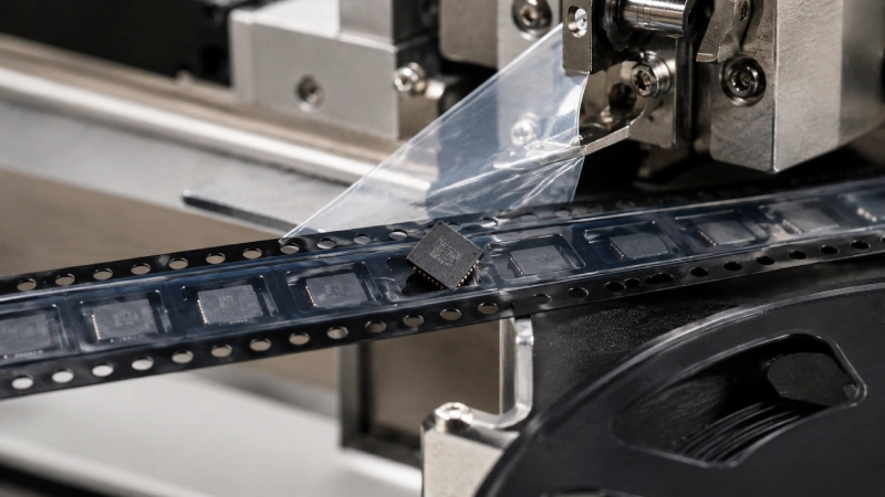
When an SMT feeder removes the cover tape, each component should remain stable inside its carrier pocket until the pick-and-place nozzle reaches the pickup position. In some reels, however, components suddenly rise, rotate, flip, or leave the pocket as the cover tape is peeled.
This behavior is often described as component trampolining. The term is commonly used for component pop-out associated with unstable de-taping behavior, but the cover tape is not always the only cause. Pocket clearance, feeder geometry, reel winding, static attraction, and component shape can all contribute to the same visible failure.
The correct response is not simply to reduce adhesion or change the cover tape. The reel must be evaluated as a complete packaging system. Jiushuo’s cover tape for SMT carrier packaging should therefore be matched with the actual carrier material, pocket geometry, component dimensions, sealing process, reel, and feeder conditions.
First Confirm What Type of Component Movement Is Occurring
Not every pickup failure is trampolining. Before adjusting materials or machine settings, observe exactly how the component moves and when the movement begins.
A component may:
- Jump completely out of the pocket.
- Flip or rotate but remain inside the pocket.
- Shift laterally before the nozzle arrives.
- Tilt because one edge climbs the pocket sidewall.
- Rise with the cover tape and then fall back.
- Remain correctly positioned while the nozzle or feeder causes the mis-pick.
These symptoms can look similar at normal production speed. A slow-motion video from the side and top of the peel point is usually more useful than a still photograph.
Record whether the component starts moving when the peel front reaches the pocket, when the carrier advances, when the cover tape take-up spool turns, or when the nozzle approaches. If the problem involves lifting, tearing, wrinkles, residue, or visibly uneven separation rather than component pop-out alone, first use a broader cover tape troubleshooting guide to classify the defect.
| Observed symptom | Possible mechanism | First evidence to collect |
|---|---|---|
| Component jumps as the cover tape separates | Peel-force peak, carrier vibration or poor pocket restraint | Slow-motion peel video and peel-force curve |
| Component rotates inside the pocket | Excessive lateral clearance or unsuitable pocket geometry | Component and pocket measurements |
| Component follows the cover tape | Static attraction, contamination or adhesive transfer | Microscope inspection and ESD check |
| Failure appears only on one feeder | Peel path, take-up tension or feeder condition | Reel–feeder A/B trial |
| Failure appears at regular intervals | Periodic sealing or tape-advance variation | Curve position and failed-pocket location |
What Happens at the Cover-Tape Peel Point
During feeding, the cover tape changes direction and separates from the carrier tape. This produces a peel front where the sealing interface opens while the feeder advances the carrier and winds the removed cover tape.
A stable process produces controlled separation with limited disturbance to the carrier. An unstable process may store tension in the film and release it suddenly. The resulting movement can pull or vibrate the carrier tape, disturbing components that are lightweight, shallowly seated, or free to move inside their pockets.
The pickup position also matters. If the cover tape is removed very close to the component pickup point, the part may not have enough time to settle before the nozzle arrives. If the peel point moves, the take-up system jerks, or the cover tape contacts a feeder guide, the disturbance may vary from pocket to pocket.
This is why the failure should be evaluated as a dynamic event. A laboratory result can indicate whether the tape combination has controlled peel behavior, but it cannot fully reproduce every feeder’s roller arrangement, cover plate, take-up mechanism, acceleration, and operating speed.
Root Cause 1: Peel-Force Peaks and Stick–Release Behavior
A common mistake is to evaluate only the average peel force. Two samples can have a similar average while producing very different feeder behavior.
One sample may generate a relatively smooth curve. Another may contain short peaks followed by sudden releases. Those peaks can temporarily increase tension in the tape path, while the release can transfer a small mechanical impulse to the carrier.
Possible curve patterns include:
- Isolated peaks caused by a local sealing irregularity.
- Repeating fluctuations associated with the application mechanism or pocket pitch.
- Gradual drift from the beginning to the end of a reel.
- Different behavior between the two sealing lanes.
- A sudden change near a splice, damaged edge, or contaminated area.
The complete curve should therefore be reviewed together with the average, minimum, maximum, variation range, sample position, peel angle, test speed, and conditioning history. Jiushuo’s guide to cover tape peel force and SMT feeding stability explains the broader relationship between peeling behavior and feeder reliability.
To separate a material problem from an equipment problem, compare the affected reel with a known-good reel under controlled conditions. Do not change the cover tape, feeder tension, speed, and pocket design at the same time. Change one variable and record the result.

Root Cause 2: Pocket Fit Allows the Component to Move
Even smooth cover tape peeling can disturb a component if the pocket does not control its position.
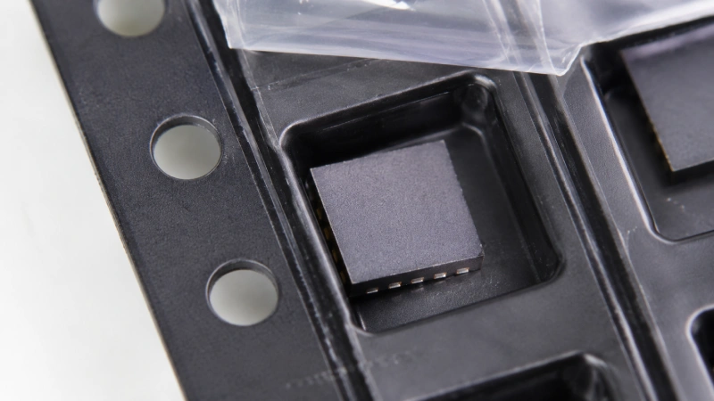
Pocket evaluation should consider the actual component dimensions and tolerances, not only the nominal package size. Review the pocket length, width and depth—commonly represented by A0, B0 and K0—together with component height, maximum outline, terminal geometry, fragile surfaces, and required pickup orientation.
Too much lateral clearance can allow rotation or impact against the sidewalls. Excessive headspace may allow the component to rise before the cover plate or cover tape restrains it. A sloped sidewall can allow a component edge to climb upward when the carrier vibrates.
Pocket-bottom geometry is also important. A curved, uneven, or poorly supported bottom can create an unstable resting position. Carrier-tape documentation from major manufacturers highlights the use of tight pocket tolerances, small sidewall draft, flat pocket bottoms, and reduced headspace to limit migration, tilting, rotation, and flipping in thin-component applications. These are product-specific design examples rather than universal dimensional rules.
When component movement is linked to pocket fit, changing the cover tape may only mask the problem. The correct action may be to evaluate a better-matched embossed carrier tape for stable SMT feeding or develop a custom carrier tape pocket design based on the component drawing and physical samples.
Root Cause 3: Peel Angle and Feeder Geometry
The peel angle used in a controlled test must not be confused with the changing geometry inside an operating feeder.
A standardized test helps suppliers compare materials under defined conditions. An actual feeder introduces additional variables, including:
- Distance between the peel point and pickup position.
- Take-up spool tension and rotation.
- Cover-tape guide and roller condition.
- Carrier support below the open pockets.
- Cover-plate clearance.
- Feeder indexing acceleration.
- Tape routing and alignment.
- Reel position relative to the feeder entrance.
The current authorized version of the applicable standard should be used when defining official test conditions. Jiushuo’s EIA-481 tape-and-reel standards guide provides an overview, but the customer specification, supplier procedure, and actual feeder setup must still be identified separately.
Do not change the feeder peel path arbitrarily. First confirm the approved routing in the feeder manufacturer’s instructions. Inspect worn rollers, contaminated guides, an over-tight take-up clutch, cover-tape rubbing, and insufficient support below the carrier.
If one reel fails on several verified feeders, the cause is more likely to follow the packaging. If several reels fail only on one feeder, the feeder path or maintenance condition deserves closer inspection.
Check Reel Winding, Tape Tracking and Carrier Camber
Component jumping may appear to occur at the peel point even when the original disturbance begins earlier in the tape path.
Check whether:
- The tape is wound evenly between the reel flanges.
- The carrier rubs against one side of the feeder.
- Cover tape alignment changes across the reel.
- Winding tension compresses or deforms deep pockets.
- The reel telescopes or becomes loose.
- The carrier develops excessive curvature or camber.
- The tape rises from the feeder track during indexing.
Carrier, cover tape, and reel should be validated together because a suitable pocket and cover tape can still feed poorly when winding or reel dimensions are incorrect. The carrier tape, cover tape and reel compatibility guide explains the checks needed before approving the complete package.
Do Not Confuse Trampolining with Static Attraction
A very small or lightweight component may rise with the cover tape even when the mechanical peel motion is relatively stable. In this case, the part may be attracted to the film by triboelectric charging rather than being mechanically launched from the pocket.
Clues include:
- Components remain attached to the peeled cover tape.
- The problem becomes more frequent under certain environmental conditions.
- Grounding or ionization changes the failure rate.
- No visible adhesive is found on the component.
- Lightweight LEDs or thin chips are affected more than heavier parts.
Inspect the center of the cover tape and the component’s upper surface under magnification. Adhesive transfer may leave visible residue or tackiness. Static attraction may occur without detectable glue contamination. Confirm the grounding of equipment, ESD controls, ionizer condition, component sensitivity, and the actual surface properties of the packaging materials.
Follow a Controlled Diagnostic Workflow
A structured investigation prevents the original evidence from being destroyed by repeated machine adjustments.
1. Quarantine the Affected Material
Preserve the failed reel, a normal reel, loose cover tape, carrier samples, labels, and original packaging. Record the cover tape lot, carrier lot, component lot, machine, feeder, reel position, storage history, and failure frequency.
2. Capture the Failure on Video
Film the reel entrance, carrier track, cover-tape peel point, exposed pocket, pickup position, and take-up spool. Use both side and top views when possible.
3. Determine Whether the Problem Follows the Reel
Use a controlled A/B trial:
| Trial | Reel | Feeder | Main purpose |
|---|---|---|---|
| A | Affected reel | Original feeder | Reproduce the baseline |
| B | Affected reel | Verified feeder | Check whether failure follows the reel |
| C | Known-good reel | Original feeder | Check whether failure follows the feeder |
| D | Known-good reel | Verified feeder | Establish the control condition |
4. Correlate the Failed Position with the Peel Curve
Mark the pocket area where the event occurred and retain the corresponding tape section. Compare it with a normal section under identical test conditions. The full method, reporting information, and interpretation boundaries are covered in Jiushuo’s EIA-481 cover tape peel force test guide.
5. Measure the Pocket and Component
Compare actual component dimensions with measured pocket dimensions. Check lateral movement, rotation, headspace, bottom support, sidewall contact, and unobstructed vertical pickup.
6. Verify One Corrective Action at a Time
Possible variables include cover tape lot, carrier lot, application process, feeder, speed, take-up tension, pocket design, grounding, and ionization. A result is not conclusive when several variables change simultaneously.
Should the Cover Tape System Be Changed?
Changing cover tape is appropriate only when evidence indicates that the existing sealing interface or peel behavior contributes to the failure.
Before switching materials, confirm:
- The cover tape is compatible with the carrier material and surface.
- Width and alignment create continuous sealing lanes.
- The application equipment matches the adhesive system.
- The seal or applied pressure is consistent across the reel.
- Storage and conditioning have not changed performance.
- Pocket fit is suitable.
- The new combination passes an actual feeder trial.
Heat-activated adhesive cover tape forms its seal through controlled heat, pressure, and time. Pressure-sensitive adhesive cover tape bonds primarily when controlled pressure is applied and normally does not require heat to activate the adhesive. Neither system is automatically the best solution for every component.
Compatibility should be qualified using the exact materials and process. Jiushuo’s guide to carrier tape and cover tape compatibility explains why supplier recommendations, industry-standard conditions, and actual production results must be kept separate.
Validate the Correction Before Mass Production
A short sample that runs successfully once is not enough for mass-production approval.
Validation should include multiple sections and, where practical, multiple reels or lots. Review the reel beginning, middle, and end. Test under defined laboratory conditions, then confirm the result on the intended feeder at representative operating conditions.
The approval record should identify:
- Cover tape and carrier tape lots.
- Application or sealing conditions.
- Test angle, speed, and conditioning.
- Full peel-force curve.
- Component movement observations.
- Residue or sticking inspection.
- Feeder model and trial result.
- Acceptance source.
- Lot-to-lot repeatability.
Most importantly, separate the applicable EIA-481 requirements, the customer’s specification, the supplier’s recommended process window, Jiushuo’s internal control criteria, and the measured result. Passing one numerical check does not automatically prove that the complete reel is feeder-ready.
What to Send Jiushuo for a Technical Evaluation
For an initial component-jumping review, provide as much of the following information as possible:
- Component drawing, datasheet, or physical samples.
- Carrier tape drawing and pocket dimensions.
- Failed and normal reel samples.
- Cover tape and carrier tape labels.
- Sealing or pressure-application process information.
- Peel-force curve with full test conditions.
- Feeder model and operating speed.
- Slow-motion failure video.
- Storage and transportation history.
- ESD requirements.
- Failure rate and reel position.
- Corrective actions already attempted.
This evidence helps determine whether the next step should focus on cover tape matching, pocket redesign, reel winding, feeder setup, ESD control, or a combined sample-validation project.
FAQ
Is component trampolining always caused by high cover tape peel force?
No. Peel-force peaks may contribute, but pocket clearance, feeder take-up behavior, peel-point geometry, carrier vibration, winding, and electrostatic attraction can produce similar symptoms.
Can a reel pass a peel-force test and still cause components to jump?
Yes. An average value may hide local peaks or periodic variation. Laboratory test geometry may also differ from the actual dynamic peel path in the customer’s feeder.
How can I tell whether a component jumped or stuck to the cover tape?
Use slow-motion video and inspect the component and cover tape under magnification. Check for residue, tackiness, grounding, and ionization. A component that remains attached to the film may indicate static attraction or adhesive transfer rather than mechanical trampolining.
Which pocket dimensions should be checked?
Review A0, B0, and K0 together with actual component tolerances, height, sidewall draft, bottom flatness, headspace, orientation, and vertical pickup clearance. A universal clearance value should not be applied to every component.
Should I switch to pressure-sensitive cover tape?
Not without validation. The decision depends on carrier material, surface condition, application equipment, adhesive construction, peel profile, ESD requirements, and actual feeder performance.
What is the most useful evidence for investigating component jumping?
A slow-motion video, failed and normal reel samples, component and pocket drawings, a full peel-force curve, test conditions, feeder details, and material lot records provide the strongest starting point.