
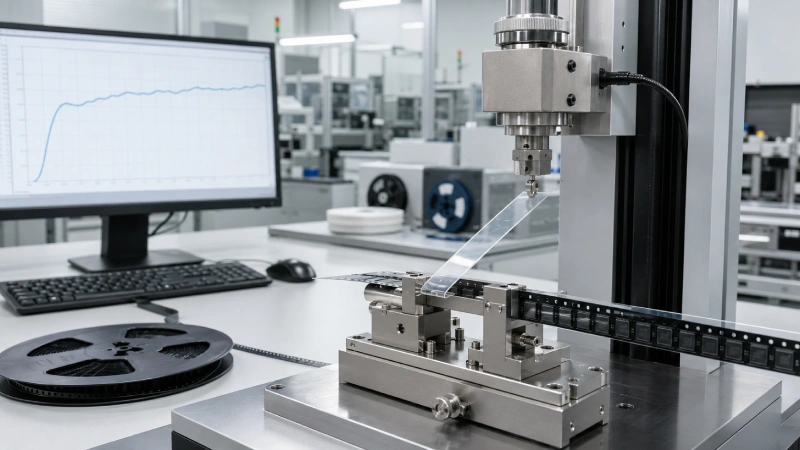
Cover tape peel force is not simply a property of the cover film. It is the measured separation force produced by a specific combination of cover tape, carrier tape material, sealing conditions, sample age, test geometry, and test speed.
A peel-force result is useful only when those conditions are controlled and recorded. Two suppliers may test the same tape combination and obtain different results if they use different peel angles, sample conditioning periods, test speeds, fixtures, or data-processing methods.
For SMT packaging buyers, quality engineers, and component manufacturers, an EIA-481 peel test should answer more than one question:
- Is the total peel strength within the applicable standard requirement?
- Is the peel force stable throughout the tested length?
- Are there localized spikes, tape tearing, adhesive transfer, or incomplete sealing?
- Can the result be reproduced across samples and production lots?
- Does the laboratory result support stable operation in an actual SMT feeder?
This guide explains how to prepare, test, interpret, and document cover tape peel force according to EIA-481. For a broader explanation of why controlled peeling matters in production, see how cover tape peel force affects SMT feeding stability.
Understand What EIA-481 Requires
EIA-481 covers dimensional, packaging, orientation, reel, carrier tape, and cover tape requirements for surface-mount components supplied for automatic handling. Companies performing formal qualification should use an authorized copy of the current standard and identify the exact revision on every test report.
The official standard can be obtained from the EIA-481-F standard page. For additional dimensional and packaging context, review Jiushuo’s EIA-481 tape-and-reel requirements.
EIA-481-F defines total cover tape peel-strength requirements according to carrier tape width:
| Carrier Tape Width | EIA-481-F Total Peel Strength |
|---|---|
| 4 mm | 0.1–0.7 N |
| 8 mm | 0.1–1.0 N |
| 12–56 mm | 0.1–1.3 N |
| 72 mm and wider | 0.1–1.5 N |
The standard also specifies a controlled pull direction, peel angle, and test speed. The cover tape is pulled opposite the direction of carrier tape travel, and the geometry is intended to reproduce a controlled seal-separation condition.
Before using any value in a qualification plan, engineers should verify the exact wording and tolerances against the authorized standard. Public summaries, old test procedures, equipment brochures, and supplier specifications should not replace the current standard.
These figures describe standard acceptance boundaries. They are not automatically the ideal internal control limits for every component, adhesive system, carrier material, or SMT feeder.
A customer may require a narrower peel-force window, additional aging tests, stricter force variation, or an actual feeder trial. A cover tape manufacturer may also use internal warning and control limits that are tighter than the outer EIA-481 boundaries.
Prepare a Traceable Test Sample
A peel-force value without sample identification has limited engineering value. Before testing, record the complete material combination and sample history.
Identify the Carrier Tape
The test record should include:
- Carrier tape width
- Carrier tape material and grade
- Carrier tape supplier
- Material lot number
- Pocket pitch and general pocket configuration
- Surface finish or coating, where applicable
- Whether components are loaded
- Sample position within the reel
- Storage and environmental exposure before testing
The same cover tape can produce different peel behavior on different carrier tape substrates. Surface energy, material formulation, flange flatness, contamination, and dimensional stability can all influence the sealed interface.
Peel force must therefore be evaluated as part of carrier tape and cover tape compatibility rather than as an isolated cover tape specification.
Identify the Cover Tape
Record:
- Product name or code
- Cover tape lot number
- Nominal width
- Adhesive system
- Anti-static or conductive configuration
- Manufacturing date
- Storage history
- Date and time of sealing
- Time between sealing and peel testing
Correct width selection is important. A tape that does not align properly with both carrier flanges may create an incomplete seal on one side or an inconsistent seal width. Review the cover tape width matching guide when preparing a new material combination.
Record the Sealing Method
The sample-preparation record must distinguish between heat-activated adhesive and pressure-sensitive adhesive systems.
A heat activated cover tape forms its seal through a controlled combination of heat, pressure, and time. Its test record should include sealing temperature, applied pressure, dwell time, sealing-head geometry, number of sealing strikes, and line speed.
A pressure sensitive cover tape bonds mainly through applied pressure and normally does not require heat to activate the adhesive. Its preparation record should include roller type, roller pressure, number of passes, application speed, surface cleanliness, and the interval between application and testing.
Specific Jiushuo product-code mapping should be confirmed by the Jiushuo technical team before model names are assigned to either adhesive category.
The 3M Static Dissipative Heat Activated Cover Tape 2690 technical data sheet demonstrates why process conditions must be documented. Its published results are tied to a specified carrier, sealing pressure, dwell time, machine, and sealing-shoe geometry. Those values describe that particular material system and must not be treated as universal sealing settings.
Condition the Samples Before Testing
Peel force can change between initial sealing and later testing. A report should state whether the sample was tested:
- Immediately after sealing
- After room-temperature storage
- After elevated-temperature aging
- After high-temperature and high-humidity exposure
- After another customer-defined conditioning cycle
Do not compare an initial result directly with an aged result unless the test objective and conditioning method are clearly stated.
After environmental exposure, samples may also require a defined recovery or stabilization period before testing. The correct procedure should come from the approved customer specification, supplier test method, or internal quality-control plan.
When comparing suppliers, buyers should verify that all samples were conditioned in the same way. A lower initial peel force and a higher post-aging peel force may reflect normal adhesive development, environmental influence, or a test-method difference. It should not be interpreted without the full sample history.
Prepare the Peel-Force Tester
Use a calibrated tester that can hold the carrier tape securely, maintain the required peel geometry, move at a controlled speed, and continuously record force.
A suitable cover tape peel strength tester should provide more than a single force reading. Ideally, the system should capture the complete force curve and calculate minimum, maximum, average, range, and standard deviation where required.
Before testing, verify:
- Equipment identification number
- Calibration status and due date
- Load-cell or strain-gauge range
- Measurement unit
- Zero-force reading
- Fixture condition
- Programmed pull speed
- Test length and sample identification
Equipment suppliers such as GPD Global describe peel-back force systems that record minimum, maximum, average, speed, standard deviation, and a continuous force profile. This illustrates the value of retaining curve data instead of approving a material from one displayed number.
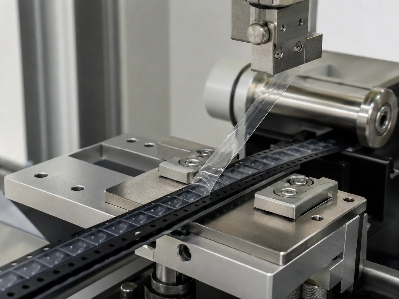
The test fixture should support the carrier tape without adding uncontrolled friction. The peel point should remain stable, and the pull direction should stay aligned with the cover tape. A changing angle or moving peel point can distort the recorded force.
Run the Cover Tape Peel Test
1. Inspect the Sealed Sample
Before loading the sample, inspect the seal under suitable lighting.
Look for:
- Edge lifting
- Wrinkles
- Misalignment
- Contamination
- Interrupted seal bands
- Tape damage
- Carrier tape deformation
- Splices within the proposed test section
Do not ignore a visible defect simply because the measured average may later fall within the numerical acceptance range.
2. Install the Carrier Tape
Place the carrier tape in the tester so it follows the intended support path without twisting or lateral rubbing.
The carrier tape should remain flat enough to maintain a stable peel point. Excessive bending, fixture friction, or poor alignment can add external forces and distort the measurement.
3. Attach the Cover Tape
Separate enough cover tape to connect it securely to the force sensor or clamp.
Make sure:
- The film does not slip inside the clamp.
- The clamp does not cut or stretch the cover film.
- The tape is aligned with the direction of pull.
- No uncontrolled preload is applied before zeroing.
4. Confirm the Test Geometry
The cover tape must be pulled opposite the carrier tape travel direction while maintaining the EIA-481 peel angle.
Before starting the test, verify:
- Pull direction
- Peel angle
- Pull speed
- Test length
- Sample number
- Force unit
- Applicable acceptance criteria
A fixture that allows the peel point or angle to change significantly during testing can produce a misleading curve.
5. Start the Test and Save the Full Curve
Begin the test at the approved speed and record force continuously through the defined evaluation length.
Do not rely only on the average. Save:
- Raw force-versus-distance or force-versus-time curve
- Minimum force
- Maximum force
- Average force
- Force range
- Standard deviation, when used
- Test speed
- Evaluated test length
The report should also explain whether the initial transition and final section were included or excluded from the calculation.
6. Inspect the Peeled Materials
After testing, inspect both the cover tape and carrier tape.
Check for:
- Adhesive residue on the carrier flange
- Film tearing
- Film stretching
- Adhesive-layer separation
- Carrier tape damage
- Uneven separation between the two seal bands
- Local areas with no effective seal
These observations can reveal a failure mode that is not obvious from the average force value.
Interpret the Peel-Force Curve
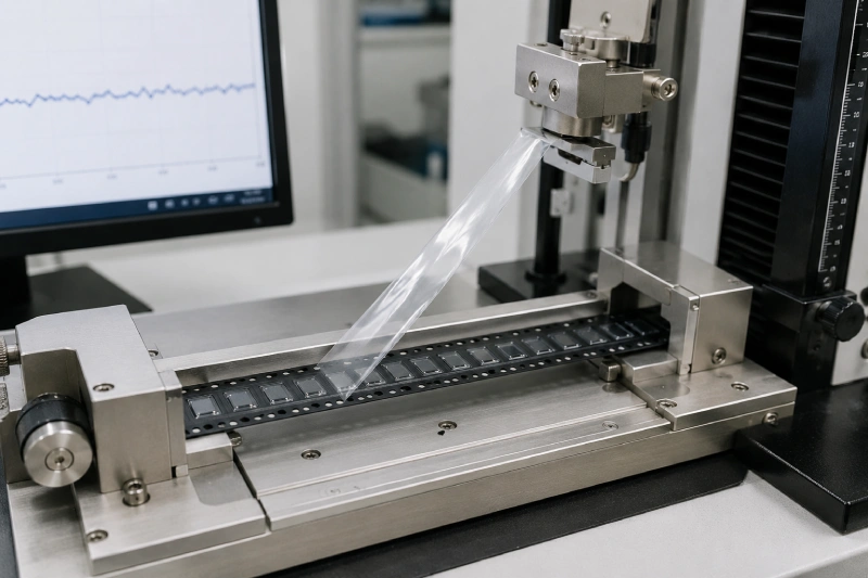
A stable curve normally shows controlled separation with limited variation throughout the evaluated section. It should not contain repeated severe spikes, sudden force drops, or long sections near the rejection boundary.
Consistently High Force
Possible investigation areas include:
- Excessive sealing temperature
- Excessive pressure
- Excessive dwell time
- Incompatible carrier surface
- Sample aging
- Incorrect test speed
- Incorrect peel angle
- Adhesive transfer or cover-film deformation
These are investigation directions, not automatic conclusions. The tester setup should be checked before changing the tape or sealing process.
Consistently Low Force
Check for:
- Insufficient heat input for a heat-activated system
- Insufficient roller pressure for a pressure-sensitive system
- Contaminated carrier flanges
- Incomplete adhesive contact
- Misaligned cover tape
- Uneven carrier tape flange geometry
- Testing too soon after application, where relevant
Spikes or Saw-Tooth Variation
Localized spikes may be associated with interrupted sealing contact, wrinkles, flange roughness, contamination, equipment vibration, or unstable test geometry.
An acceptable average can hide these defects. Several high peaks may be mathematically balanced by low-force sections even though the resulting reel could peel unevenly in production.
Tape Tear or Adhesive Transfer
Tape tearing, delamination, or visible residue should be investigated even when total peel strength falls inside the standard range. Such defects may contaminate feeder guides, interrupt continuous peeling, or alter component exposure at the pick-up point.
Decide Whether the Sample Passes
A proper acceptance decision uses several layers of requirements.
First, compare the result with the width-specific EIA-481 range.
Second, apply any customer-specific specification. The customer may require a narrower force window, tighter variation, environmental aging, specific sample quantities, or testing from multiple reel positions.
Third, apply the supplier’s approved internal control criteria. Internal production limits may be narrower than EIA-481 so that process drift can be detected before the material reaches an external rejection boundary.
Finally, review the visual observations and complete force curve. Passing the average-force requirement does not automatically override tape tearing, residue, edge lift, or severe variation.
A single passing sample confirms only that the tested specimen met the defined criteria under the recorded conditions. It does not demonstrate lot-to-lot capability. Process capability claims require sufficient data from multiple samples and production lots.
What Should Be Included in the Test Report?
A professional peel-force report should contain:
| Report Field | Why It Matters |
|---|---|
| Standard and revision | Confirms the applicable test method |
| Carrier tape width, material, and lot | Identifies the tested substrate |
| Cover tape product and lot | Supports traceability |
| Sealing method and parameters | Allows the sample to be reproduced |
| Conditioning history | Distinguishes initial and aged results |
| Equipment and calibration status | Confirms measurement control |
| Peel angle and pull speed | Confirms test geometry |
| Number of samples and test length | Shows sampling coverage |
| Minimum, maximum, and average | Summarizes the force result |
| Complete force curve | Reveals variation and localized defects |
| Visual inspection | Records residue, tearing, or incomplete sealing |
| Acceptance criteria and conclusion | Explains the pass/fail decision |
Buyers should be cautious when a supplier report contains only one average value without material identification, sealing parameters, sample age, or curve data.
For incoming inspection, the test report should also show whether the sample came from the beginning, middle, or end of a reel. This helps identify variation caused by winding, sealing setup changes, or material transitions.
When Should Cover Tape Peel Force Be Retested?
Retesting may be appropriate after:
- A carrier tape material or supplier change
- A cover tape lot or adhesive-system change
- A cover tape width change
- A sealing-temperature, pressure, dwell-time, or line-speed change
- A roller or sealing-head replacement
- Sealing-machine maintenance
- Extended storage or environmental exposure
- A customer complaint involving lifting, residue, tearing, or uneven peel
- A feeder problem involving component jumping or unstable cover tape removal
The retest plan should identify whether the purpose is material qualification, process validation, shelf-life review, incoming inspection, or failure analysis. Each purpose may require a different sampling plan.
Peel Testing Does Not Replace Feeder Validation
An EIA-481 peel test evaluates the separation force under a controlled laboratory geometry. It does not evaluate every variable present in an SMT feeder.
Actual feeding performance can also be affected by:
- Component mass and center of gravity
- Pocket clearance and component rotation
- Carrier tape flatness and camber
- Reel winding tension
- Feeder peel-point position
- Electrostatic charge
- Machine acceleration
- Production speed
For lightweight ICs, QFNs, LEDs, sensors, or components that have already shown jumping or rotation, a laboratory peel test should be followed by a feeder trial using the intended packaging configuration.
When feeder instability occurs, review both the peel-force data and the broader carrier tape feeding problems that may influence component presentation.
Validate the Complete Tape Combination Before Production
The most reliable approach is to test the actual cover tape, carrier tape, sealing process, storage condition, and feeder environment as a complete system.
Jiushuo supplies cover tape for carrier tape packaging and supports material matching, sample preparation, peel-force checking, and tape-and-reel packaging evaluation.
To review a new project or investigate an unstable peel result, provide:
- Carrier tape width and material
- Cover tape identification
- Component drawing or physical sample
- Sealing equipment and process settings
- Customer peel-force specification
- Existing test curve or report
- Defect photographs or feeder video
- Expected production quantity
Testing the complete combination before mass production helps separate material issues from process, equipment, and test-method variation. It also gives buyers and suppliers a clearer technical basis for sample approval and production release.
FAQ
Does EIA-481 use the same peel-force limit for every carrier tape width?
No. EIA-481 defines different total peel-strength ranges for different carrier tape widths. The applicable value should be confirmed against the current authorized standard and any customer-specific requirements.
Can heat-activated and pressure-sensitive cover tapes use the same peel-force test?
The sealed tape combinations may be evaluated using the applicable EIA-481 peel method, but their sample-preparation records are different. Heat-activated systems require controlled heat, pressure, and time, while pressure-sensitive systems mainly require controlled application pressure and surface conditions.
Why can two laboratories obtain different peel-force results from the same reel?
Differences may come from peel angle, test speed, calibration, fixture alignment, sample conditioning, evaluated test length, data filtering, or the way initial and final portions of the curve are handled.
Is average peel force enough to approve a cover tape lot?
No. Buyers should also review minimum and maximum force, curve stability, tape tearing, adhesive residue, seal appearance, sample traceability, and any required customer criteria.
Should peel force be tested immediately after sealing or after aging?
It depends on the qualification objective. Initial, room-temperature-aged, and environmentally conditioned tests answer different questions, so the report must identify the sample condition and time between sealing and testing.
Can a passing EIA-481 peel test guarantee stable SMT feeder performance?
No. Feeder performance is also affected by pocket fit, component movement, carrier flatness, reel tension, static charge, peel-point position, machine settings, and production speed.
What should a buyer submit for cover tape peel-force validation?
Submit the carrier tape width and material, cover tape identification, sealing settings, component drawing or sample, customer acceptance criteria, existing test data, and any defect photographs or feeder video.