
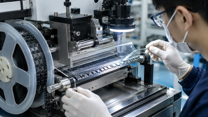
A cover tape defect is rarely caused by one variable alone. Lifting may result from insufficient sealing, but it can also come from incorrect width, flange contamination, poor alignment, carrier tape warpage, storage exposure, or an incompatible material combination. Tearing may indicate excessive peel resistance, yet it can also begin at a damaged film edge or a sharp feeder guide.
The fastest way to solve these problems is not to change several machine settings at once. Preserve the evidence, classify the failure pattern, isolate possible causes, and verify one change at a time. This guide covers lifting, tearing, wrinkles, adhesive residue, and uneven peel in both heat-activated and pressure-sensitive systems. For product matching or sample validation, review Jiushuo’s cover tape solutions for SMT packaging.
Start by Quarantining the Affected Reels
Before changing temperature, pressure, roller position, or web tension, stop the process and identify the affected material. Record the cover tape lot, carrier tape lot, machine, production time, reel position, and defect location. Note whether the problem appears at the reel start, in the middle, near a splice, or only after storage, shipping, or feeder use.
Keep both failed and normal samples. A comparison reel from the same project helps separate material variation from machine or environmental changes.
At minimum, collect:
- Defect photos and a peeling video
- Cover tape and carrier tape labels
- Carrier tape material and nominal width
- Cover tape width and sealing method
- Machine model and application mechanism
- Relevant process settings
- Storage history
- Peel-force data with test speed and peel angle
- The reel section where the defect occurred
Do not repeatedly adjust several variables before capturing this information. Otherwise, the original failure condition may be impossible to reproduce.
Identify the Defect Before Assigning a Cause
“Poor sealing” is not a sufficient defect description. Record the pattern, location, and timing of the problem.
| Observed Defect | Pattern to Record | First Checks |
|---|---|---|
| Lifting | One edge, both edges, intermittent, immediate, or after aging | Alignment, seal-band continuity, flange condition, material match |
| Tearing | Edge crack, transverse break, longitudinal split, or feeder-point damage | Peel path, film damage, guide contact, local force spikes |
| Wrinkles | Diagonal, transverse, longitudinal, edge wave, or telescoping | Web path, tension, roller parallelism, reel clearance |
| Residue | Continuous transfer, spots, tacky film, or surface damage | Microscopy, contamination, adhesive-zone position, thermal history |
| Uneven peel | Random spikes, periodic oscillation, gradual drift, or reel-position change | Test conditions, sealing variation, tension, local contamination |
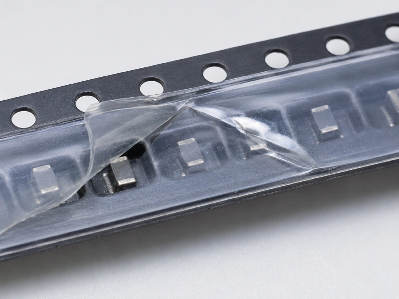
Lifting or an Incomplete Seal?
Determine whether a proper seal band was never formed or whether the tape sealed initially and later released. One-sided lifting often points toward alignment, tape width, roller or sealing-shoe parallelism, or an uneven carrier flange. Two-sided or intermittent lifting requires a broader review of pressure, material compatibility, contamination, carrier flatness, and storage history.
A nominally correct width can still create incomplete contact if the tape is offset or the flange geometry differs from the validated design. Jiushuo’s cover tape width matching guide for carrier tape explains the width, flange, and sprocket-hole relationships that should be checked.
Film Tearing or Carrier Tape Surface Failure?
Locate where the tear begins. If it starts at the film edge, inspect for nicks, reel-flange contact, excessive overhang, or guide interference. If it begins near the feeder peel point, check the peel path and contact with sharp or misaligned machine parts.
A damaged carrier flange can resemble adhesive residue or cover tape failure. Examine both peeled surfaces under magnification. Whitening, fibers, fragments, or delamination may indicate carrier surface failure rather than cover film breakage.
Wrinkles or Tracking Skew?
Follow the cover tape from unwind to sealing and take-up. Identify the first point where the wrinkle appears. Diagonal wrinkles may suggest web skew or unequal tension, while repeated transverse creases may be associated with a cyclic roller, pressure, or winding issue. These are diagnostic clues, not universal conclusions.
Reel width, side clearance, winding tension, overhang, and carrier tracking can interact. Review the carrier tape, cover tape and reel compatibility guide when the problem becomes worse as the reel builds or appears near one flange.
Separate Heat-Activated and Pressure-Sensitive Failure Paths
Heat-activated adhesive cover tape forms its seal through a controlled combination of heat, pressure, contact time, and line speed. Pressure-sensitive adhesive cover tape bonds mainly through applied pressure and adhesive wet-out, normally without heat activation.
| Diagnostic Variable | Heat-Activated System | Pressure-Sensitive System |
|---|---|---|
| Primary activation | Controlled heat and pressure | Pressure and surface contact |
| Main equipment checks | Actual temperature, dwell time, rail condition, pressure distribution | Roller condition, alignment, pressure distribution |
| Main surface checks | Flange flatness and thermal response | Cleanliness, wet-out, adhesive-zone contact |
| Common mistake | Raising temperature without confirming the cause | Applying heat without product-specific approval |
For heat activated cover tape, check the complete process window rather than the temperature setting alone. Compare the displayed temperature with the actual sealing condition, and inspect rail flatness, left-to-right pressure, warm-up stability, dwell time, and line speed.
Official manufacturer sheets, such as the Advantek HUG heat-activated cover tape data sheet, show why published values should be treated as product-specific laboratory or reference conditions rather than universal machine settings.
For pressure sensitive cover tape, inspect the roller or pressure shoe, carrier flange cleanliness, adhesive-zone alignment, and contact uniformity. The Advantek PUC pressure-sensitive cover tape data sheet identifies roller application at ambient temperature for that specific series. This should not be transferred automatically to another product, but it illustrates why PSA troubleshooting should focus on pressure and wet-out rather than assuming that higher heat is the answer.
Never transfer settings between the two adhesive systems. A corrective action that improves a heat-activated seal may damage or destabilize a pressure-sensitive material.
Troubleshooting Cover Tape Lifting
Use the location and timing of the lift to narrow the investigation:
- One continuous lifted edge: Check alignment, cover tape width, roller or sealing-head parallelism, and flange geometry.
- Both edges lifting: Confirm tape orientation, application method, material match, and overall pressure or thermal process.
- Intermittent lifting: Look for contamination, carrier warpage, cyclic pressure variation, or tension changes.
- Lifting after storage or shipping: Review initial seal quality, aging, environmental exposure, winding, and package compression.
- Lifting near a splice: Examine local thickness, tension disturbance, and contact pressure.
Do not use higher heat or pressure to hide a material mismatch. Carrier tape composition, surface properties, and flange condition can affect adhesion. When the problem continues after alignment and process checks, evaluate carrier tape and cover tape compatibility with actual production samples.
After an adjustment, run a short controlled trial. Keep other variables unchanged and compare seal appearance, lift frequency, peel-force curve, and feeder behavior. If the original problem occurred after storage or transport, immediate appearance alone is not enough to approve production.
Troubleshooting Cover Tape Tearing
Cover tape tearing can result from excessive or locally unstable peel resistance, but mechanical damage must be ruled out first. Inspect the film edge, reel flange, guides, rollers, sealing area, and feeder peel point.
A small edge nick can develop into a complete break under tension even when the average peel force appears acceptable. Excessive cover tape overhang can also cause the film to contact guides or reel flanges.
Check whether tearing corresponds to isolated peaks in the peel-force curve. If the break occurs at repeatable intervals, investigate:
- Periodic machine-pressure variation
- Roller surface damage
- Repeating carrier tape geometry
- Local contamination
- Wrinkle formation
- Reel winding defects
- Splices or changes in material thickness
If tearing begins beside a wrinkle, the wrinkle may be concentrating stress. If the cover tape remains intact but the carrier flange shows whitening, fibers, or delamination, the carrier tape surface may be failing instead.
Troubleshooting Wrinkles and Misalignment
For wrinkles, trace the web path in order:
- Reel mounting and unwind drag
- Guide alignment
- Roller parallelism
- Carrier tape tracking
- Sealing-shoe or pressure-roller contact
- Take-up and winding tension
Find the first point at which the wrinkle appears. A wrinkle visible before the sealing point is unlikely to be corrected by changing adhesive settings.
Diagonal wrinkles may indicate web skew, unequal tension, or poor guide alignment. Repeated transverse wrinkles may be associated with a rotating roller defect, cyclic pressure, or uneven take-up. Longitudinal edge waves can be related to tape curl, excessive overhang, uneven contact, or compression near a reel flange.
Change only one controlled variable at a time. Reducing tension may remove a wrinkle but create tracking instability. Increasing pressure may improve contact while deforming the carrier flange or creating another crease.
Troubleshooting Adhesive Residue and Component Sticking
Record whether the suspected residue appears on the carrier tape sealing flange, within the cover tape adhesive zone, or in the component-facing center area. These locations represent different possible causes and risks.
Use magnification before describing the material as adhesive residue. Compare the abnormal reel with a known-good reel and inspect both peeled surfaces. Dust, oil, damaged carrier material, and transferred adhesive can look similar without close examination.
Component sticking also does not automatically prove adhesive transfer. A Vishay application note on avoiding ChipLEDs sticking to cover tape describes microscopic inspection used to check for contamination or glue residue and discusses triboelectric charging as another possible contributor. This is particularly relevant for very light components that move during peeling.
For heat-activated systems, review uneven thermal input, dwell time, pressure, and possible carrier surface damage. For pressure-sensitive systems, review wet-out, adhesive-zone alignment, storage exposure, roller condition, and feeder contamination.
Do not reduce every residue problem to “temperature too high.” The residue must first be identified and its location confirmed.
Diagnose Uneven Peel from the Curve, Not Only the Average
A single average value can hide short peaks or progressive drift. Evaluate the complete curve and classify the pattern:
- Isolated spikes: Local contamination, wrinkles, splices, edge damage, or discrete seal defects
- Periodic oscillation: Cyclic pressure, roller defects, repeating geometry, or winding variation
- Gradual drift: Temperature drift, tension changes, reel buildup, or environmental change
- Differences between reel sections: Process instability, storage exposure, or lot variation
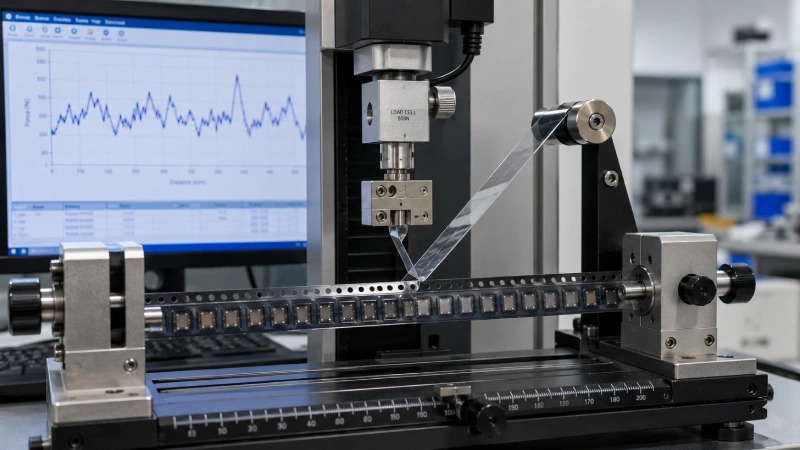
Keep test conditions constant. Record sample position, test speed, peel angle, conditioning, equipment, and calculation method. Compare the reel start, middle, end, defect area, and a normal area.
A supplier’s internal control range, a customer specification, and an EIA-481 test requirement are not interchangeable. Jiushuo’s guide to cover tape peel force and SMT feeding stability explains why both the force level and its consistency affect feeder behavior.
For broader information on standard requirements and test interpretation, refer to the EIA-481 tape-and-reel standards guide.
Avoid Corrective Actions That Create Another Defect
A process adjustment can solve one symptom while creating a second problem.
Increasing heat may improve an incomplete heat-activated seal, but excessive or uneven thermal input may also increase peel resistance, damage the carrier flange, or contribute to transfer. Increasing pressure may improve contact, but it can also create wrinkles or carrier deformation.
Reducing adhesion may prevent tearing but increase the risk of lifting during storage and transport. Lowering web tension may reduce wrinkles while allowing the tape to track sideways.
For this reason, every corrective trial should change one variable while keeping the others controlled. The result should be evaluated visually, mechanically, and in the intended feeder process.
Verify the Corrective Action Before Releasing Production
Repeat testing under the same conditions used for the baseline. Confirm more than visual sealing:
- Continuous seal bands without lifting
- No tearing or wrinkle formation
- No confirmed adhesive transfer
- Stable peel-force behavior
- Component retention during handling
- Smooth feeder peeling without component displacement
When the original defect appeared only after storage, transport, or environmental exposure, include suitable conditioning and retesting based on customer requirements, supplier guidance, and internal quality procedures.
Document the suspected cause, variable changed, variables held constant, test results, feeder performance, and release decision. If the failure cannot be reproduced or remains unstable, do not approve mass production based on appearance alone.
What to Send Jiushuo for Technical Evaluation
Effective troubleshooting requires enough evidence to reproduce the condition. Send:
- Affected and normal tape samples
- Component drawings or physical samples
- Carrier tape material and dimensions
- Cover tape width
- Machine model
- Application or sealing settings
- Storage and transportation history
- Peel-force curves and test conditions
- Defect photographs
- A slow-motion peeling or feeder video
- Cover tape and carrier tape lot labels
Jiushuo can review the combination and help plan a matched cover tape and carrier tape evaluation. The goal is not simply to replace one reel, but to validate the cover tape, carrier tape, sealing process, winding condition, and feeder behavior as a complete tape-and-reel system.
FAQ
Can cover tape lifting always be corrected by increasing sealing temperature?
No. First identify whether the material is heat activated or pressure sensitive. Lifting may also come from poor alignment, insufficient pressure, contamination, incorrect width, flange deformation, storage exposure, or material incompatibility.
How can adhesive residue be distinguished from carrier tape damage?
Inspect both peeled surfaces under magnification and compare them with a normal sample. Carrier fragments, whitening, or delamination indicate a different failure from tacky adhesive transfer. Laboratory analysis may be required when visual evidence is inconclusive.
Why does peeling become unstable near the end of a reel?
Possible contributors include temperature or tension drift, reel buildup, side compression, tracking changes, winding pressure, or variation across the sealed length. Compare curve data and machine records from the beginning, middle, and end of the reel.
Can heat be used with pressure-sensitive cover tape?
Only when the product supplier explicitly approves it. Many PSA systems are designed for pressure application at ambient conditions. Heat-activated process settings should not be applied automatically to pressure-sensitive products.
What evidence should be sent to a cover tape supplier?
Provide lot labels, failed and normal samples, clear photos, a peeling video, carrier material, cover tape width, machine and process details, storage history, defect location, and raw peel-force data with complete test conditions.