
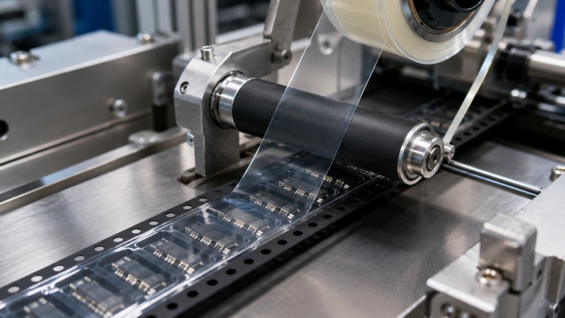
Pressure-sensitive adhesive cover tape is widely used in SMT tape-and-reel packaging because it can be applied through controlled pressure without activating the adhesive with heat. However, “pressure sensitive” does not mean that the tape can simply be placed over a carrier tape and pressed down using any convenient machine setting.
Stable application depends on the complete interface between the adhesive stripes and the carrier tape sealing lanes. Surface condition, tape orientation, width matching, roller geometry, alignment, web tension, line speed, and pressure distribution can all affect seal continuity and subsequent peel behavior.
A successful setup must therefore be validated as a system. The operator should confirm the materials, record the equipment conditions, run a short first-article trial, and test the finished combination before approving full-reel production.
First Confirm That the Tape Is Truly Pressure Sensitive
Before adjusting a roller or loading material onto the packaging machine, confirm that the selected product is genuinely a pressure-sensitive adhesive cover tape.
A typical PSA cover tape uses adhesive stripes near its two edges. Pressure applied over these stripes brings the adhesive into close contact with the corresponding sealing lanes on the carrier tape. Unlike heat-activated adhesive cover tape, the adhesive does not normally require a defined sealing temperature to become active.
The 3M Pressure Sensitive Cover Tape 2698 technical data describes room-temperature application and states that heat is not recommended for that specific product. Advantek similarly lists a roller and ambient temperature as reference application conditions for its PUC pressure-sensitive cover tape. These documents illustrate the industry distinction, but their product-specific settings must not be copied directly to another supplier’s material.
This confirmation is particularly important when product names have been translated differently or when internal model names do not clearly identify the adhesive system. Never determine the application method from the model code alone. The adhesive construction and approved process must be confirmed through the product specification or by the supplier’s technical team.
For projects requiring pressure-based room-temperature application, review Jiushuo’s pressure sensitive cover tape for SMT packaging and request product-level confirmation before setting the machine.
Build an Application Setup Record before Running Material
A repeatable application process requires more than a single pressure value. Before starting the trial, prepare a setup record covering the materials, equipment, and production environment.
At a minimum, record:
- Cover tape product code, width, and lot number
- Carrier tape material, width, and production lot
- Adhesive stripe position or width, when available
- Applicator or packaging machine model
- Roller or reciprocating shoe configuration
- Displayed pressure and unit
- Line speed
- Web tension setting
- Roller width, hardness, and condition
- Ambient temperature and relative humidity
- Date, operator, and trial identification
The displayed machine pressure must be treated carefully. A pneumatic gauge reading does not necessarily represent the actual pressure at the adhesive interface. Cylinder size, roller width, roller compliance, mechanical losses, and machine construction can all change the force delivered to the tape.
The 3M technical data for its 2698 product notes that gauge-pressure readings can vary among equipment manufacturers. It also explains that a roller and a reciprocating mechanism can produce different results under apparently identical settings because their pressure distribution differs.
The setup record should distinguish three categories:
| Condition Type | Purpose |
|---|---|
| Supplier reference condition | Starting guidance for the specified product |
| Trial condition | Setting evaluated on the actual machine and carrier tape |
| Approved production condition | Validated setting released for repeat manufacturing |
Do not present a competitor’s application range as a universal PSA requirement. The Advantek PUC Series bulletin, for example, publishes reference conditions for its own product and test setup. Those values are not automatically applicable to a Jiushuo product or a customer’s production line.
Material selection should also be reviewed before the application trial. The carrier substrate and adhesive must be evaluated together, as explained in this guide to carrier tape and cover tape compatibility.
Prepare the Carrier Tape Surface and Sealing Lanes
The functional bonding areas are the narrow sealing lanes on both sides of the carrier tape pockets. These areas deserve more attention than the center of the pocket.
Before applying cover tape, inspect both sealing lanes for:
- Dust or loose particles
- Oil, fingerprints, or handling marks
- Scratches and surface damage
- Carrier tape flange deformation
- Pocket-edge distortion
- Residue from previous processing
- Inconsistent sealing-lane width
- Moisture or contamination caused by poor storage
Even a small particle can prevent local adhesive contact. The finished tape may appear sealed from a distance while containing a short unbonded section that later becomes an edge-lifting point during winding, transport, or feeder operation.
Avoid touching the carrier tape flanges or adhesive stripes with bare fingers. Operators should handle the material through the reel core, non-functional edges, or other approved handling areas. Gloves must also be clean and suitable for the packaging environment.
Do not recommend a general-purpose solvent without confirming that it is compatible with the carrier tape and adhesive system. An aggressive cleaner may attack PS, PC, PET, or another substrate, change the surface, leave residue, or create dimensional distortion.
Materials transferred from cold, hot, or humid storage should be allowed to stabilize under the approved production environment before use. The conditioning period must come from the applicable supplier specification or internal validation rather than a generic recommendation.
Align the Cover Tape with Both Sealing Lanes
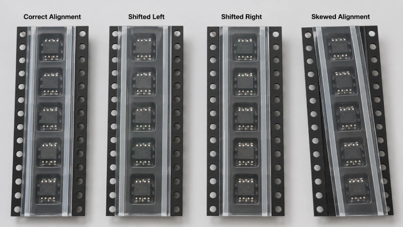
Correct alignment is not simply a matter of placing the cover tape centerline over the center of the carrier tape.
The operator must verify that both adhesive edge stripes sit over usable sealing lanes. A tape can look centered while one adhesive stripe partially overlaps a pocket wall, falls outside the flange, or approaches the sprocket-hole area.
Check the following before applying full pressure:
- Correct unwind direction
- Adhesive side facing the carrier tape
- Equal and continuous contact on the left and right sealing lanes
- Clearance from pocket openings
- Clearance from sprocket holes
- No excessive cover tape overhang
- Stable tracking through guides and rollers
Do not identify the adhesive side only by film transparency, color, or appearance. Follow the product label, roll-direction mark, construction drawing, or supplier instruction.
The selected cover tape width also affects the available alignment window. A dimensionally suitable tape provides adequate coverage without entering functional pocket or sprocket-hole areas. For width selection rather than application setup, refer to the cover tape width matching guide.
Alignment should be inspected over a running length, not only at the starting point. Lateral drift may develop gradually because of incorrect guide position, miscentered reels, uneven web tension, roller skew, carrier tape camber, sudden line-speed changes, or damaged reel flanges.
Pressure should not be used to compensate for poor tracking. Stabilize the tape path and guides first; otherwise, higher pressure may only lock a misaligned cover tape more firmly into the wrong position.
Apply Pressure over the Adhesive Stripes
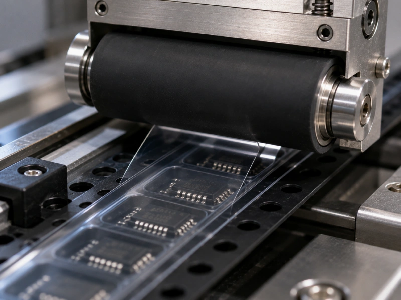
The application mechanism should place controlled and reasonably uniform pressure over the two adhesive zones.
The primary force should not be concentrated over the pocket opening. Applying excessive force at the center may deflect the cover film toward the component, especially when the pocket contains a tall device or when clearance is limited.
Before the trial, inspect the roller for:
- Adequate width to contact both adhesive lanes
- Parallelism relative to the carrier tape
- Surface cleanliness
- Cuts, dents, or hardened contamination
- Uniform rotation
- Excessive wear
- Appropriate compliance for the application
A compliant roller can accommodate small variations in the carrier tape surface, but roller hardness and deformation still require control. A roller that is too rigid may produce local loading, while a damaged or contaminated roller may create periodic pressure variation.
Roller parallelism is particularly important. When one side of the roller contacts the material more strongly than the other, one adhesive stripe may form a continuous bond while the opposite edge remains weak. The result is often one-sided lifting or left-to-right peel-force imbalance.
Pressure must also be established together with line speed. A faster process changes the effective contact time, while an unnecessarily slow process may reduce productivity without solving material incompatibility. The correct combination should be determined through a controlled trial on the intended machine.
Do not add heat simply because initial adhesion appears low. For conventional PSA cover tape, heat is not the activation mechanism. Unapproved heating may change the film, adhesive behavior, carrier tape dimensions, or subsequent peel performance. Any temperature-assisted condition for a specific Jiushuo model must be confirmed by the Jiushuo technical team before use.
Run a Short First-Article Trial
Do not seal a complete production reel immediately after loading a new cover tape, carrier tape lot, or machine setup.
Run a short trial section that is long enough to evaluate tracking, visual seal continuity, initial winding, and peel behavior. Record the exact machine settings used for the trial.
Inspect both adhesive lanes for:
- Continuous contact
- Similar appearance on both sides
- Edge lifting
- Wrinkles or folds
- Bubbles
- Tape drift
- Adhesive squeeze-out
- Contact between the cover tape and components
- Interference with sprocket holes
- Excessive overhang beyond the carrier tape edge
The inspection should continue after the taped carrier has been wound onto the reel. A combination that looks acceptable while lying flat may behave differently under winding tension. Watch for shifting, edge lifting, or distortion near the reel flange.
Cover tape is only one part of the finished package. After sealing, the carrier tape and reel must still operate as a coordinated system. Additional checks are discussed in the carrier tape, cover tape and reel compatibility guide.
Validate Peel Performance under Defined Conditions
A visually continuous seal does not automatically guarantee stable feeder performance. The first-article sample should undergo peel evaluation under a documented test method.
The peel test record should identify:
- Cover tape and carrier tape combination
- Material lot numbers
- Time between application and testing
- Test temperature and humidity
- Peel angle
- Peel speed
- Tested length
- Test equipment and load cell
- Initial, aged, or post-storage condition
Application pressure and peel force are different measurements. Roller pressure describes how the tape was applied; peel force describes the force required to remove it afterward. They should never be reported as interchangeable values.
When reviewing a peel curve, do not evaluate only the average. Look for maximum and minimum values, sudden spikes, periodic fluctuations, increasing or decreasing force along the length, left-to-right differences, corresponding wrinkles or alignment changes, and adhesive transfer after peeling.
The test result must be compared with the approved product specification, COA requirement, or customer acceptance criteria. Supplier technical data should only be used when the material combination and test conditions match the referenced product.
For a broader explanation of why variation matters during component exposure, see how cover tape peel force affects SMT feeding stability.
When EIA-481 is referenced, distinguish the standard’s packaging and test requirements from a supplier’s internal process window. The current applicable document and customer requirements should be reviewed directly rather than relying on an unsupported claim of compliance. Jiushuo’s EIA-481 tape-and-reel standards guide provides an overview of the dimensions, peel considerations, and packaging elements that must be coordinated.
Diagnose Problems by the First Visible Symptom
Application defects should be investigated systematically rather than corrected by immediately increasing pressure.
| Symptom | First Items to Check |
|---|---|
| One edge lifts | Alignment, roller parallelism, pressure distribution, surface contamination |
| Both edges show weak contact | Material identification, pressure delivery, roller contact, carrier surface |
| Wrinkles develop | Web tension, guide position, roller skew, unwind direction |
| Tape drifts laterally | Reel centering, guides, carrier camber, changing tension |
| Peel force is spiky | Local contamination, wrinkles, roller damage, misalignment, test setup |
| Adhesive transfers | Material compatibility, storage, pressure, carrier surface, peel conditions |
| Components move during peel | Peel variation, pocket fit, component clearance, feeder setup |
One-sided lifting is often associated with asymmetric conditions. Raising total pressure may strengthen one side while failing to correct the weak side. Check whether both adhesive stripes are properly positioned and whether the roller is parallel before changing the setting.
Wrinkles usually indicate a tape-path or tension problem. Confirm the unwind direction, guide locations, and roller alignment. Sudden acceleration or unstable web tension can also create temporary folds that later produce peel-force spikes.
Adhesive residue should not automatically be blamed on excessive pressure. It may involve the adhesive formulation, carrier surface, storage history, contamination, or peel-test conditions. Document where the residue appears and retain samples from the affected lot.
Release the Process for Production
A successful sample is not yet a production process. Before mass production, convert the accepted trial into a controlled operating window.
The released setup should define:
- Approved cover tape and carrier tape combinations
- Approved machine or applicator type
- Documented pressure setting and unit
- Line-speed range
- Web-tension control
- Alignment checkpoints
- Environmental conditions
- First-piece inspection criteria
- Peel-test method and frequency
- Conditions requiring production to stop
Revalidation should be considered after a change in cover tape construction, carrier tape material, roller, machine, width, production speed, or storage condition.
Lot traceability is equally important. Record the cover tape lot, carrier tape lot, operator, machine, date, trial result, and peel-test reference. This allows quality teams to distinguish a material issue from an equipment or setup change if problems later occur.
Request an Application Review before Mass Production
When PSA cover tape application remains unstable, send the supplier enough information to evaluate the complete packaging interface rather than only the cover tape part number.
Useful information includes:
- Component drawing or physical samples
- Carrier tape drawing and material
- Carrier tape samples
- Current cover tape specification
- Tape width and adhesive-stripe information
- Applicator and roller details
- Displayed pressure and unit
- Line speed and web tension
- Defect photographs or video
- Peel-force curve and test conditions
- Target reel and production requirements
Jiushuo can review these details as part of a pressure-sensitive cover tape sample validation project. Confirming the material combination, alignment method, and application conditions before full production is more reliable than attempting to correct peel or lifting problems after complete reels have already been packaged.
FAQ
Does pressure-sensitive cover tape require heat during application?
A typical PSA cover tape is applied through controlled pressure and does not require heat to activate the adhesive. Any temperature-assisted condition for a specific product must be confirmed in its technical specification.
How should roller pressure be selected for PSA cover tape?
Start with the product-specific supplier recommendation, then validate the setting on the actual machine, roller, carrier tape, line speed, and test method. One pressure value should not be treated as universal.
Can the same roller setting be used for different carrier tape materials?
It should not be assumed. Carrier material, surface condition, stiffness, flange geometry, and adhesive compatibility can change the required setup and peel result.
How can I tell whether the cover tape is correctly aligned?
Check that both adhesive stripes remain over the usable sealing lanes and stay clear of pocket openings, sprocket holes, and carrier edges over a representative running length.
Why does one side of the cover tape lift while the other side remains sealed?
Common causes include tape misalignment, roller skew, uneven pressure distribution, carrier flange deformation, surface contamination, or an adhesive stripe that is not fully supported by the sealing lane.
Should peel force be tested immediately after application?
Follow the approved product or customer test method. The record should state conditioning time, temperature, humidity, peel angle, peel speed, equipment, and whether the sample is initial, aged, or post-storage.
What should be sent to a supplier for application troubleshooting?
Provide the carrier tape drawing and material, component information, cover tape specification, machine and roller details, pressure and speed settings, defect photos or video, and peel-force data with complete test conditions.