
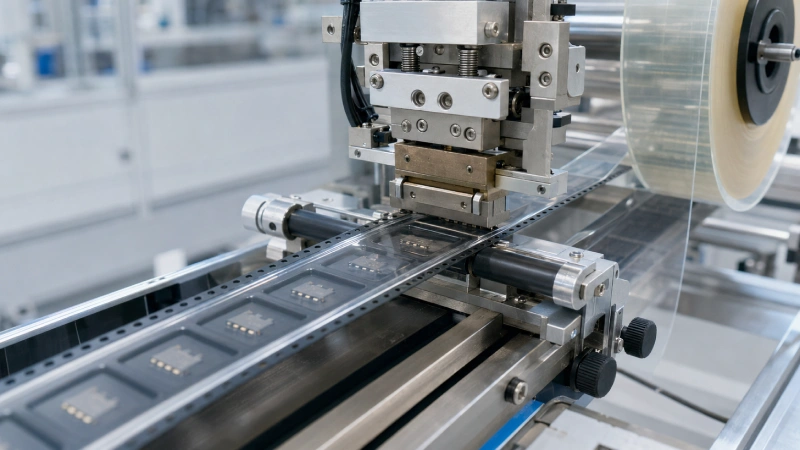
Heat-activated cover tape does not have one universal sealing recipe. A temperature that works with one carrier tape may produce weak adhesion, excessive peel force, or carrier deformation with another. Even when the same materials are used, different sealing machines can produce different results because of seal-rail geometry, temperature sensing, pressure distribution, and contact time.
A reliable process therefore begins with a specific system: the cover tape, carrier tape, sealing equipment, and intended production speed. The objective is not to create the strongest possible bond. It is to establish a repeatable sealing window that keeps components contained during handling and transport while allowing smooth, controlled peeling during SMT feeding.
Readers who need a basic introduction to the material and its construction can first review this guide to heat-seal cover tape fundamentals.
Start with the Tape Pair and Sealing Machine
Heat-activated adhesive cover tape uses controlled heat, pressure, and contact time to form a bond along the flanges of the carrier tape. This is different from pressure-sensitive adhesive cover tape, which primarily bonds through applied pressure and normally does not require heat to activate the adhesive.
Before adjusting any machine settings, confirm:
- The cover tape adhesive system
- The carrier tape material
- The cover and carrier tape widths
- The sealing mode
- The sealing-head or seal-rail geometry
- The target packaging speed
- The required peel behavior
- The test method used to evaluate the result
Carrier tapes made from PS, PC, PET, PVC, or other materials can respond differently to heat and pressure. Their surface properties, flange flatness, thickness, and thermal response influence how the adhesive forms a seal. For this reason, the carrier tape and cover tape compatibility must be evaluated as a complete system.
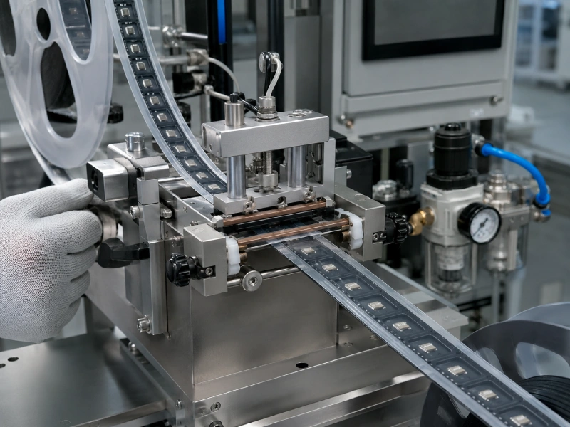
The sealing machine is equally important. Intermittent sealing, multiple-strike sealing, continuous heated shoes, and heated rollers do not create identical thermal and pressure conditions. Two machines displaying the same temperature and pressure may produce different seals if their contact areas, sensor locations, or pressure mechanisms differ.
How the Four Sealing Parameters Form One Process Window
Temperature, pressure, dwell time, and line speed should not be treated as four independent settings. They interact to determine how much heat reaches the adhesive, how uniformly the tape contacts the carrier flange, and how stable the final peel force becomes.
| Parameter | What Must Be Confirmed | Risk When Insufficient | Risk When Excessive |
|---|---|---|---|
| Temperature | Setpoint, actual head temperature and temperature uniformity | Incomplete adhesive activation or partial sealing | Carrier deformation, excessive adhesion or adhesive damage |
| Pressure | Machine setting, seal-head alignment and contact distribution | Discontinuous seal bands and edge lifting | Rail marks, deformation or excessive compression |
| Dwell time | Actual contact time, strike count and sealing mode | Insufficient heat transfer | Excessive thermal exposure and reduced output |
| Line speed | Stable speed and effective time inside the heated area | Reduced heat exposure at higher speeds | Not normally a direct over-processing cause, but compensation settings may become excessive |
These effects are possible outcomes, not automatic diagnoses. Material mismatch, contamination, tape misalignment, and equipment condition must also be investigated.
Temperature: Setpoint Is Not Interface Temperature
The temperature displayed by the controller is not necessarily the temperature at the adhesive–carrier interface.
Heat must pass from the sealing head through the cover tape backing before reaching the heat-activated adhesive. The actual heat delivered to the seal depends on:
- Heater design and sensor location
- Seal-head material and mass
- Warm-up and recovery time
- Temperature uniformity across the sealing rails
- Cover tape construction
- Carrier tape material and thickness
- Contact time and production speed
A low temperature may leave part of the adhesive insufficiently activated. However, automatically increasing the setpoint can conceal other problems, such as inadequate contact pressure or a warped carrier flange. Excessive thermal input can also distort the carrier tape or push the process toward unnecessarily high peel force.
The 3M 2690 technical data sheet explicitly notes that sealing temperature depends on the equipment, dwell time, pressure, and carrier material. This principle should be applied to any supplier’s recommended range: it is a starting reference, not a universal production setting.
Pressure: Uniform Contact Matters More Than the Gauge Number
Pressure brings the adhesive layer into contact with the carrier tape flange. The important condition is the pressure distributed along both sealing lines—not only the value shown on an air-pressure regulator.
Pressure performance can be affected by:
- Seal-head parallelism
- Rail width and surface condition
- Cylinder or spring mechanism
- Carrier tape flatness
- Cover tape alignment
- Dust, burrs, or contamination on the flange
- Wear on the sealing head
If one side of the cover tape lifts while the other side remains sealed, check alignment and pressure distribution before changing temperature. Higher pressure cannot reliably correct incompatible materials or insufficient adhesive activation. It can also produce visible rail marks or deform thin carrier tape.
Dwell Time: Define the Actual Contact Period
Dwell time must be defined according to the sealing mode.
On an intermittent machine, dwell time may refer to how long the heated head remains pressed against each indexed section. A multiple-strike process must also record the number of strikes. On a continuous system, the more useful value is the effective time that a given section of tape remains within the heated contact area.
Manufacturer data demonstrates why the full test condition matters. The Advantek HUE technical data sheet provides reference sealing conditions together with the specific product construction, compatible carrier materials, dwell time, pressure, and seal-rail width. Those values apply to that product and should not be copied as specifications for a different cover tape.
Line Speed: Convert Speed into Effective Heat Exposure
Increasing line speed can reduce the time available for heat transfer in a continuous sealing system. This may shift a stable seal toward incomplete activation even though the displayed temperature and pressure remain unchanged.
For a continuous-contact system, effective contact time can be estimated only when the heated contact length and tape speed are known. For intermittent equipment, index speed and sealing dwell may be controlled separately, so the same calculation may not apply.
Production speed should be evaluated at:
- Start-up
- Normal steady operation
- Planned target speed
- Planned maximum speed
- Acceleration and deceleration
- Restart after a short stoppage
Raising temperature to compensate for faster production may work within a validated window, but it should not be treated as an automatic rule. The revised settings must still be checked for peel stability, carrier deformation, and seal appearance.
How to Establish the Initial Sealing Window
The initial process should be developed through controlled trials rather than repeated, undocumented machine adjustments.
1. Lock the Materials and Equipment Conditions
Use the same cover tape lot, carrier tape material, tape width, sealing head, and sample-conditioning method throughout the first trial. Record the ambient conditions if temperature or humidity could influence the materials or measurement.
Changing both materials and machine parameters at the same time makes the result difficult to interpret.
2. Screen the Main Parameters
Begin with supplier reference information when it is available, but identify it clearly as a starting condition. Conduct controlled trials that move from under-processed conditions toward an apparently stable seal.
For every trial, record:
- Temperature setting
- Pressure setting
- Dwell time or strike count
- Line speed
- Seal-band appearance
- Tape alignment
- Carrier deformation
- Peel-force result
- Peel-curve stability
The first screening should identify obviously weak, potentially usable, and excessive processing regions. It should not be used to approve mass production.
3. Use a Small Trial Matrix
Once the approximate usable area is known, test combinations around the intended production condition.
| Trial ID | Temperature Level | Pressure Level | Dwell or Speed Level | Seal Appearance | Peel Result | Decision |
|---|---|---|---|---|---|---|
| A | Low | Center | Center | Record result | Record curve | Reject or continue |
| B | Center | Center | Center | Record result | Record curve | Candidate |
| C | High | Center | Center | Record result | Record curve | Check over-processing |
| D | Center | Low | Center | Record result | Record curve | Compare uniformity |
| E | Center | Center | Target speed | Record result | Record curve | Production candidate |
“Low,” “Center,” and “High” must be defined for the specific tape, machine, and carrier material. They should not be published as Jiushuo product values without verified factory data.
4. Select the Center of a Stable Window
The best production setting is rarely the condition with the highest peel result. A setting near the edge of the process window may fail when the equipment drifts slightly or a new material lot is introduced.
Select a condition that provides:
- Continuous seal bands
- Acceptable peel performance
- Low variation across the sample
- No edge lifting
- No carrier deformation
- No tearing or adhesive transfer
- Stable results at the intended line speed
- Sufficient margin from both under-sealing and over-sealing boundaries
If you are evaluating heat-activated cover tape for SMT packaging, provide the carrier tape material, tape width, sealing-machine model, sealing mode, and target speed when requesting a sample evaluation.
Validate the Output, Not Just the Machine Settings
A parameter recipe is not validated until the sealed tape has been inspected and tested.
Inspect the Seal Band
Before performing a peel test, examine both sealing lines for:
- Continuous and uniform width
- Cover tape offset
- Partial adhesion
- Wrinkles or bubbles
- Seal-rail marks
- Edge lifting
- Carrier tape warpage
- Interference with sprocket holes or pockets
A visually defective seal should not be approved simply because one peel-force reading falls within the required range.
Document Peel-Test Conditions
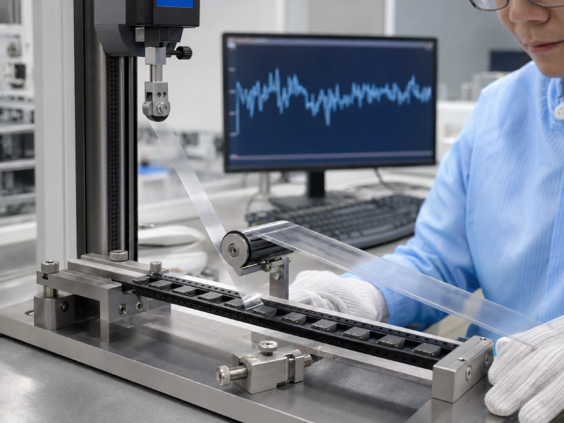
The sealing line speed and the peel-test speed are different parameters. A valid peel-force report should identify the peel speed, peel angle, sample conditioning, carrier width, sample location, and test equipment.
The current EIA-481 tape-and-reel standard specifies cover-tape peel requirements and test conditions for relevant carrier tape widths. It does not provide a universal sealing temperature, pressure, dwell time, or production speed.
Jiushuo’s EIA-481 tape-and-reel requirements guide can provide additional packaging context, while this article on cover tape peel force and SMT feeding stability explains why smooth, consistent peeling matters during placement.
Review the Entire Peel Curve
An average value can hide short peaks, periodic variation, or abrupt release points. Review the full curve and compare samples from different locations, including the beginning, middle, and end of a run.
A stable average combined with large peaks may still cause feeder vibration or disturb lightweight components.
Run Handling and Feeder Trials
Final validation should simulate the intended use. Check whether the seal remains intact during winding, storage, handling, and unwinding. Run the reel at the intended feeder conditions and observe:
- Tape vibration at the peel point
- Cover tape tearing
- Component rotation or jumping
- Feeder alarms
- Irregular release
- Residue near the sealing flange
When possible, validate with the actual component and pocket design rather than empty carrier tape alone.
Troubleshooting Parameter-Related Defects
Do not change a parameter until the likely cause has been checked.
| Symptom | Possible Parameter Cause | Other Possible Cause | Recommended Check |
|---|---|---|---|
| Edge lifting | Insufficient heat, dwell, or uneven pressure | Contamination, misalignment or incompatible materials | Inspect both seal bands and flange condition |
| High peel force | Excessive thermal input or contact time | Aggressive material pairing or incorrect test method | Review the curve and repeat under controlled conditions |
| Uneven peel force | Temperature or pressure variation | Warped carrier, rail wear or tape-width mismatch | Compare left and right seal lines |
| Wrinkles | Uneven contact or excessive compression | Poor guiding or tape tension | Inspect tape path and sealing-head alignment |
| Carrier deformation | Excessive heat or pressure | Carrier material too sensitive for the process | Check dimensions before and after sealing |
| Adhesive residue | Possible over-processing | Adhesive compatibility, aging or contamination | Inspect surfaces and test a fresh controlled sample |
Residue should not automatically be blamed on excessive temperature, and wrinkles should not automatically be treated as an adhesive problem. Alignment, guiding, winding tension, rail condition, and material compatibility may be the real causes.
Transfer the Recipe to Mass Production
A validated laboratory setting must be confirmed again when it is transferred to another machine or production line.
Verify:
- Temperature calibration and sensor position
- Seal-head material and dimensions
- Pressure mechanism
- Dwell-time definition
- Heating recovery during continuous operation
- Tape guiding and tension
- Actual target speed
Establish first-piece approval after start-up, material changes, maintenance, and extended stoppages. Revalidation should also be considered after changing a cover tape lot, carrier tape material, seal rail, machine, or production speed.
Routine production records should include the approved recipe, visual inspection, peel-force sampling, deviations, and corrective action. This makes it possible to distinguish random defects from gradual process drift.
What to Send for Technical Confirmation
For an effective sealing review, provide:
- Carrier tape material and width
- Cover tape information
- Sealing-machine brand and model
- Sealing mode and seal-rail dimensions
- Current temperature, pressure, dwell, and speed
- Target production speed
- Peel-test method and curve
- Defect photographs or feeder video
- Actual carrier tape samples when available
Jiushuo can then evaluate the material combination and recommend an appropriate sample-validation direction. Customers still need to confirm the final recipe on their actual equipment before mass production.
For projects that have not yet selected a sealing system, review the available cover tape options for carrier tape packaging or request a matched heat-activated sample for testing with the intended carrier tape.
FAQ
Can I use a supplier’s recommended sealing temperature directly?
Use it only as a starting reference. Confirm the carrier material, equipment, pressure, dwell time, seal-rail geometry, and test conditions behind the recommendation.
Does a faster line speed always require a higher temperature?
No. A faster continuous process may reduce effective heat exposure, but the correct response depends on the equipment and available process window. Revalidate the full parameter combination.
Can higher pressure correct cover tape lifting?
Not always. Lifting may come from inadequate heat, short dwell, poor alignment, contamination, flange deformation, or material incompatibility.
Can one recipe be used for PS, PC and PET carrier tape?
Do not assume so. Different carrier materials and surface constructions may require different sealing conditions. Test the actual tape pair.
Does EIA-481 define the heat-sealing recipe?
No. EIA-481 defines relevant tape-and-reel packaging and peel requirements. The sealing recipe must be established for the specific materials and equipment.
When should the process be requalified?
Requalification should be considered after material, lot, equipment, seal-head, speed, maintenance, storage, or customer-requirement changes.