
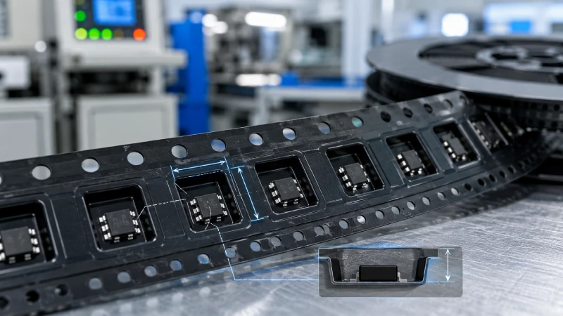
When buyers talk about carrier tape pocket design, three dimensions are usually mentioned first: A0, B0 and K0. These values may look like technical codes, but the basic idea is simple. A0 means the pocket width, B0 means the pocket length, and K0 means the pocket depth. Together, they define the space where a component sits inside the carrier tape.
For SMT packaging engineers, these dimensions affect feeding reliability and pick-and-place performance. For component suppliers and procurement teams, they affect whether the packaging can protect the product, reduce movement during transport, and support stable automated assembly. If the pocket is too loose, the component may rotate or tilt. If the pocket is too tight, the component may be difficult to load or may become damaged. If the pocket is too shallow or too deep, pickup problems can happen during SMT assembly.
This guide explains A0, B0 and K0 in a simple and practical way. It is written for buyers, suppliers, and packaging teams who need to understand carrier tape pocket dimensions without going too deep into engineering formulas.
What Do A0, B0 and K0 Mean in Carrier Tape?
A carrier tape pocket is the cavity that holds each component in place. The pocket must be large enough for the component to enter smoothly, but it also needs to control movement. The goal is not only to “fit” the part into the pocket. The real goal is to keep the part stable, protected, correctly oriented, and easy for the SMT nozzle to pick.
A0 refers to the inside width of the pocket. It controls side-to-side clearance. B0 refers to the inside length of the pocket. It controls movement along the feeding direction. K0 refers to the pocket depth. It controls how deeply the component sits inside the pocket.
These three values are especially important for embossed carrier tape because embossed pockets are formed to match the shape and packaging needs of the component. For standard rectangular components, the pocket may look simple. But for connectors, sensors, precision metal parts, relays, crystal oscillators, power modules, or other non-standard components, pocket design may need to be customized.
Simple Carrier Tape Pocket Dimension Guide
The table below gives a simple explanation of the most common carrier tape pocket and tape layout dimensions.
| Dimension | Simple Meaning | Why It Matters |
|---|---|---|
| A0 | Pocket width | Controls side-to-side fit and helps reduce rotation or lateral movement |
| B0 | Pocket length | Controls front-to-back fit and helps maintain component orientation |
| K0 | Pocket depth | Controls how deeply the component sits and affects protection and pickup height |
| W | Carrier tape width | Must match component size, pocket layout, reel format, and feeder compatibility |
| P1 | Pocket pitch | Distance between pocket centers; affects feeding position and SMT machine indexing |
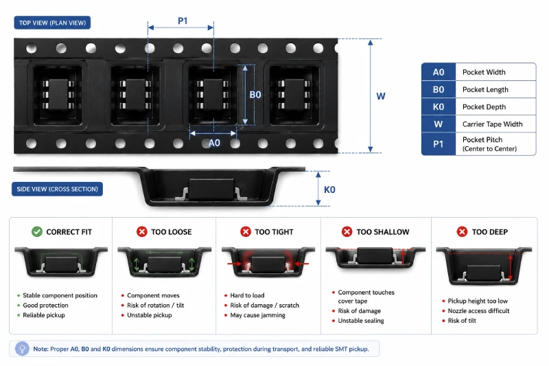
A0, B0 and K0 describe the pocket itself. W and P1 relate more to the carrier tape format and SMT feeding layout. All of them work together. Even if the pocket size is correct, the tape width and pitch still need to match the feeding equipment and packaging requirement.
For buyers ordering tape and reel packaging, it is useful to understand these basic terms before confirming a custom carrier tape design. This helps avoid misunderstandings during drawing review, sample approval, and mass production.
Why A0 Matters: Pocket Width and Side Stability
A0 is the pocket width. It controls how much space the component has from side to side. If A0 is too large, the component may shift inside the pocket during winding, transport, or feeding. This can lead to unstable positioning when the SMT machine tries to pick the part.
A loose A0 may cause several practical problems. The component may rotate inside the pocket. It may lean against one side wall. It may arrive under the cover tape in a different position from pocket to pocket. For high-speed SMT assembly, this lack of consistency can create pickup errors.
On the other hand, A0 should not be too tight. If the side clearance is too small, the component may not drop smoothly into the pocket during loading. It may scrape against the pocket wall, become scratched, or jam inside the tape. For components with fragile leads, soft surfaces, sharp edges, or plastic housings, a tight pocket can create unnecessary packaging risk.
This is why A0 should be selected based on the real component shape, not only the maximum width shown on a datasheet. Some parts have protruding pins, irregular outlines, sensitive sides, or surfaces that should not be squeezed. In these cases, custom carrier tape may be needed to create a pocket that supports the part without forcing it into a simple rectangular cavity.
Why B0 Matters: Pocket Length and Orientation Control
B0 is the pocket length. It controls how the component sits in the direction of tape feeding. Like A0, it must provide enough clearance for loading, but not so much space that the part moves freely inside the pocket.
If B0 is too long, the component can move forward and backward during transport. This movement may look small, but it can affect pickup position. When the component is not consistently located inside each pocket, the SMT nozzle may not contact the correct area. For small or precision components, this can become a real production issue.
B0 is also important for orientation control. Many electronic components must face one direction before they enter the SMT process. If the pocket length does not control the part properly, the component may rotate or sit at an angle. This is especially important for connectors, terminals, sensors, crystal oscillators, and other parts with asymmetric shapes.
If B0 is too short, the component may be difficult to insert into the pocket. It may press against the pocket wall or sit unevenly. In some cases, the component may interfere with the cover tape sealing area. Good B0 design helps the component load smoothly, stay aligned, and remain ready for automatic pickup.
For buyers, the key point is simple: B0 should support both fit and direction. A pocket that only allows the part to enter is not enough. The pocket should also help the component remain in the correct orientation from packaging to SMT feeding.
Why K0 Matters: Pocket Depth, Protection and Pickup
K0 is the pocket depth. It determines how deeply the component sits inside the pocket. This dimension is very important for taller, thicker, heavier, or fragile components, but it also matters for low-profile parts.
If K0 is too shallow, the component may sit too high in the pocket. The top of the component may press against the cover tape, creating stress during sealing, winding, or transport. The part may also become unstable because it is not properly supported by the pocket walls. For components with lenses, pins, leads, or sensitive surfaces, shallow pockets can increase the risk of damage.
If K0 is too deep, the component may sit too low. This can make SMT pickup more difficult because the nozzle may not reach the correct pickup surface consistently. Deep pockets may also allow the component to tilt if the bottom support is not well designed. In some cases, a deep pocket protects the component during transport but creates problems during assembly.
K0 should therefore balance protection and pickup access. The component needs enough depth to be protected, but not so much depth that the SMT machine struggles to pick it. This is also why K0 should be reviewed together with cover tape selection. The cover tape must seal properly without pressing too strongly on the component, and the peel force must remain suitable for stable feeding.
For tall components, K0 is often one of the most important design points. For fragile components, the pocket may need extra clearance around sensitive areas. For heavy components, the pocket may need enough depth and support to reduce movement inside the reel.
How A0, B0 and K0 Affect SMT Feeding Reliability
SMT feeding depends on repeatability. Each component should be in a similar position from pocket to pocket. When the carrier tape moves through the feeder, the machine expects the component to be located in a predictable place and at a predictable height.
If A0, B0 or K0 is not suitable, the part may move before pickup. It may rotate, tilt, bounce, or shift during transport. These problems can lead to nozzle misalignment, pickup failure, feeder interruption, or unstable assembly performance.
Good pocket dimension design helps reduce these risks. A suitable A0 limits side movement. A suitable B0 helps maintain orientation along the feeding direction. A suitable K0 controls height and protection. Together, they help the component remain stable from loading to sealing, winding, shipping, unwinding, and SMT pickup.
This is why embossed carrier tape dimensions should not be selected only by checking the component’s length, width, and height. The packaging team should also consider component weight, shape, surface sensitivity, required orientation, feeder compatibility, and cover tape matching.
Common Mistakes When Choosing Carrier Tape Pocket Dimensions
One common mistake is choosing a pocket that is too loose. Buyers may think more clearance is safer because the component can be loaded easily. However, too much space inside the pocket can cause rotation, movement, and unstable pickup. A loose pocket may reduce loading pressure, but it can increase feeding problems later.
Another mistake is choosing a pocket that is too tight. A tight pocket may look stable at first, but it can create loading difficulty, scratches, deformation, or jamming. For components with leads, pins, coatings, or fragile edges, a tight pocket may cause quality issues before the product even reaches the customer.
A third mistake is ignoring component height. Some buyers focus mainly on A0 and B0 because length and width are easy to see. But K0 is just as important. A pocket that is too shallow may cause contact with the cover tape. A pocket that is too deep may create pickup difficulty. For SMT packaging, height control is not optional.
Another mistake is using standard carrier tape for non-standard parts. Standard pockets may work for common chip components, but they may not work well for irregular, tall, heavy, or fragile components. If the component has an unusual shape, special orientation requirement, or sensitive surface, custom embossed tape is often a better choice.
Finally, some buyers confirm pocket dimensions without testing samples. A drawing review is important, but sample verification is also valuable. Actual samples can reveal practical issues such as movement, loading difficulty, pickup access, or cover tape contact.
When Do You Need Custom Embossed Carrier Tape Dimensions?
Custom pocket dimensions are usually needed when standard carrier tape cannot hold the component securely or safely. This often happens with components that are irregular in shape, taller than standard parts, heavier than normal, or sensitive to pressure and movement.
For example, connectors may have plastic bodies, pins, and uneven shapes. Sensors may have delicate sensing areas. Metal stamped parts may have thin profiles or sharp edges. Relays and fuses may require deeper pockets because of their thickness. Power components may need stronger pocket support because of size and weight.
In these cases, the carrier tape pocket should be designed around the real part. A0, B0 and K0 may need to be adjusted to control movement, protect sensitive areas, and support reliable SMT pickup. This is where custom carrier tape design becomes important.
Custom embossed carrier tape can help improve part stability, reduce transportation movement, and support smoother automatic feeding. It is not only a packaging choice. It is part of the component delivery and assembly process.
What Information Should Buyers Provide Before Confirming A0, B0 and K0?
To choose suitable A0, B0 and K0 dimensions, suppliers need more than a basic part name. The more accurate the input information, the easier it is to design a stable and practical pocket.
Buyers should provide the component drawing if available. A drawing helps confirm length, width, height, and special features. A 3D file can be even more helpful for irregular components. Physical samples are also very useful because they allow the packaging team to check real shape, weight, surface condition, and loading behavior.
A datasheet can provide additional information, especially for electronic components with defined orientation or handling requirements. Buyers should also explain the required orientation inside the tape, the expected quantity per reel, and any known SMT feeder requirements.
It is also important to identify sensitive areas. For example, some components have pins that should not be pressed, lenses that should not touch the cover tape, or surfaces that should avoid friction. If the packaging supplier understands these areas early, the pocket can be designed to reduce contact risk.
Cover tape requirements should also be discussed. The pocket and cover tape work together. A good pocket design may still fail if the cover tape does not seal properly or creates too much pressure on the component.
Jiushuo can help evaluate suitable A0, B0 and K0 dimensions based on component drawings, datasheets, physical samples, orientation requirements, and packaging needs. For buyers who are not sure whether standard tape is enough, sharing samples or drawings is usually the fastest way to confirm the right direction.
Need Help Choosing Carrier Tape Pocket Dimensions?
Choosing A0, B0 and K0 is not only about matching the component’s outside size. It is about balancing fit, protection, orientation, cover tape sealing, and SMT feeding reliability. A good pocket should hold the component securely without damaging it, protect it during transport, and allow stable pickup during assembly.
Jiushuo supports custom carrier tape design for electronic components, connectors, sensors, precision metal parts, modules, and other standard or non-standard parts. If you are developing a new tape and reel packaging solution, Jiushuo can help review your component drawing, sample, or datasheet and recommend suitable pocket dimensions and tape format.
To start a project, you can share your component details and discuss your requirement for custom carrier tape or complete tape and reel packaging support.
FAQ
What do A0, B0 and K0 mean in carrier tape?
A0 means pocket width, B0 means pocket length, and K0 means pocket depth. These three dimensions define the main internal space of the carrier tape pocket.
Why are A0, B0 and K0 important?
They affect how the component fits inside the pocket, how stable it remains during transport, and how reliably it can be picked during SMT assembly.
What happens if the carrier tape pocket is too loose?
If the pocket is too loose, the component may move, rotate, tilt, or shift during winding, shipping, or feeding. This can lead to unstable pickup and assembly problems.
What happens if the pocket is too tight?
If the pocket is too tight, the component may be difficult to load. It may also become scratched, jammed, or damaged, especially if it has fragile leads or sensitive surfaces.
Is K0 only important for tall components?
No. K0 is important for both tall and low-profile components. It affects component protection, cover tape clearance, pickup height, and overall feeding stability.
Can Jiushuo help design A0, B0 and K0 dimensions?
Yes. Jiushuo can help evaluate A0, B0 and K0 based on component drawings, samples, datasheets, orientation requirements, and SMT packaging needs.