
In SMT production, electrostatic discharge (ESD) rarely announces itself clearly. It does not always burn components visibly or stop the line immediately. More often, it creates latent damage — microscopic defects that reduce long-term reliability.
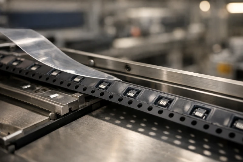
One overlooked source of ESD exposure is the carrier tape itself. During tape-and-reel handling, transportation, and high-speed feeding, friction and separation can generate significant electrostatic charge.
So the real question is not “Is anti-static carrier tape better?”
The correct engineering question is:
When is anti-static carrier tape necessary, and how do you justify that decision?
This guide focuses on practical evaluation — helping SMT engineers, packaging engineers, and technical buyers determine when upgrading to Anti-Static Carrier Tape is truly required.
Which Components Are Most Vulnerable to ESD During Tape & Reel Handling?
Not all components carry the same ESD sensitivity. The need for anti-static carrier tape begins with understanding the device itself.
Highly sensitive categories typically include:
- CMOS ICs
- MOSFETs and power management chips
- RF components
- LEDs (especially mini/micro LED)
- GaN devices
- MEMS sensors
Components with low CDM (Charged Device Model) ratings are especially vulnerable during automated handling. In tape-and-reel applications, the component can become charged inside the pocket. When the pick nozzle contacts the part, rapid discharge may occur.
Smaller packages (e.g., 0201 ICs, wafer-level CSP) are often more susceptible due to reduced internal protection structures.
If your devices fall into lower CDM classifications or are intended for high-reliability applications (automotive, medical, aerospace), the risk profile changes significantly. In such cases, using standard Carrier Tape without static control can introduce unnecessary reliability exposure.
What Is the Real Difference Between Standard and Anti-Static Carrier Tape?
The difference is not visual — it is electrical.
Standard embossed carrier tape (often PS or PET based) may have surface resistance levels that allow charge accumulation. Under friction, electrostatic voltage can build up and remain on the tape surface.
Anti-static carrier tape, by contrast, is engineered to control surface resistance within a defined dissipative range. This allows charge to bleed off gradually rather than accumulate.
The distinction typically involves:
- Material additives blended into resin
- Permanent dissipative compounds
- Surface-treated anti-static coatings
However, not all anti-static approaches are equal. Some humidity-dependent coatings lose effectiveness in dry environments (<40% RH). Permanent dissipative materials offer more stable performance across conditions.
When evaluating between standard Embossed Carrier Tape and anti-static variants, the key factor is not material type alone — it is electrical behavior stability over your actual production conditions.
Why Does High-Speed SMT Feeding Increase Static Risk?
Static generation increases with motion and friction. High-speed SMT lines amplify both.
During feeding:
- The tape slides against feeder rails
- Cover tape peeling creates charge separation
- Rapid pocket indexing increases friction cycles
- Low humidity production floors reduce charge dissipation
At 8mm pitch with high-speed placement, charge accumulation can occur repeatedly within seconds.
Importantly, ESD damage from feeding rarely causes immediate catastrophic failure. Instead, it can weaken internal junctions or gate oxides, leading to early-life failure in the field.
If your production line operates at high placement rates, especially in dry climates or controlled humidity rooms, anti-static tape becomes less of a “nice to have” and more of a preventive engineering control.
How Can You Tell If Static Is Already Affecting Your Yield?
Upgrading materials without validation is not good engineering practice. Before switching to anti-static carrier tape, confirm whether static is contributing to yield fluctuation.
Common evaluation methods include:
Surface Resistance Testing
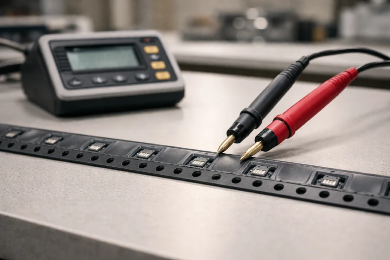
Measure tape surface resistance using a megohmmeter to confirm whether it falls within dissipative range.
Electrostatic Field Measurement
Use a field meter to measure voltage on tape during feeding simulation.
Process Correlation Analysis
Examine whether yield variation correlates with:
- Low humidity periods
- Tape supplier batch changes
- Increased placement speed
Latent Failure Indicators
Monitor early-life reliability data. A spike in infant mortality may signal hidden ESD exposure.
If testing reveals persistent charge accumulation or voltage spikes during peeling and feeding, transitioning to Anti-Static Carrier Tape becomes a data-supported decision rather than an assumption.
Anti-Static vs Dissipative vs Conductive Tape — Which One Is Right?
Not every application requires conductive material.
Three general electrical categories exist:
- Anti-static (temporary charge suppression)
- Dissipative (controlled resistance range allowing gradual discharge)
- Conductive (very low resistance materials)
For most SMT packaging applications, dissipative range materials provide balanced protection. Fully conductive tapes are typically reserved for extremely sensitive semiconductor devices.
Over-specifying conductive materials can increase cost and introduce secondary risks, such as unintended grounding interactions or mechanical performance changes.
The correct choice depends on:
- Component CDM level
- Production humidity control
- Handling environment
- Required reliability level
Selecting the right electrical classification should be part of the packaging engineering decision — not a default upgrade.
When Is Anti-Static Carrier Tape Not Necessary?
There are valid scenarios where anti-static tape may not be required.
Examples include:
- Passive components with higher ESD tolerance
- Controlled high-humidity production environments
- Low-speed assembly lines
- Facilities with comprehensive ESD flooring and grounding systems
If testing confirms minimal charge generation and stable yield performance, standard Carrier Tape may remain sufficient.
Engineering decisions should be risk-based, not trend-based.
How to Integrate ESD Requirements in Custom Carrier Tape Design?
When developing Custom Carrier Tape, ESD considerations should be defined at the beginning of the design phase — not after tooling is finalized.
Material selection affects:
- Forming behavior
- Pocket dimensional stability
- Thickness control
- Mechanical strength
Switching to anti-static resin after mold validation can impact pocket geometry and tolerance consistency.
Therefore, during custom tape development:
- Define component ESD sensitivity level
- Confirm required surface resistance range
- Validate forming compatibility
- Perform electrical and dimensional verification together
Integrating ESD control early prevents costly redesign cycles and ensures packaging performance aligns with device reliability requirements.
Conclusion
Anti-static carrier tape is not automatically required in every SMT application.
However, when handling ESD-sensitive ICs, operating high-speed placement lines, or producing high-reliability electronics, static risk becomes a measurable engineering variable — not a theoretical concern.
The correct approach is systematic:
- Evaluate component sensitivity
- Measure real electrostatic behavior
- Match electrical classification to risk level
- Integrate ESD requirements into packaging design early
By treating carrier tape as an active part of your ESD control strategy — rather than just a transport medium — you reduce hidden reliability exposure and strengthen long-term product performance.