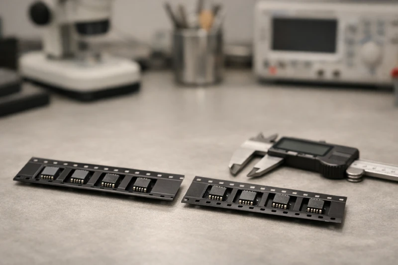
Selecting the right carrier tape for electronic components is not simply a matter of matching width or choosing a standard reel. Carrier tape selection directly affects SMT feeding stability, pick-and-place accuracy, and overall production consistency. A mismatch between component geometry and pocket design can lead to tilting, rotation, or mispicks at high line speeds. In sensitive applications, improper material choice may also increase ESD risk.
For SMT engineers and packaging decision-makers, the key question is how to evaluate component characteristics and production conditions before committing to a design. This guide outlines practical criteria for choosing carrier tape based on component dimensions, stability requirements, material considerations, and validation steps.
What Component Parameters Actually Determine Carrier Tape Selection?
Carrier tape selection should begin with a clear understanding of the component. Package length, width, and height define the basic pocket size, but tolerance ranges are equally critical. Engineers must evaluate maximum and minimum dimensional limits to prevent excessive clearance or tight fit, both of which can reduce positional stability during SMT feeding.
Component weight and center of gravity influence how parts behave inside the pocket. Lightweight chips may tolerate minimal clearance, while taller or asymmetrical components are more prone to tilting if lateral support is insufficient. For uneven mass distribution, pocket depth and wall geometry become important in maintaining consistent orientation during transport and indexing.
Lead configuration and surface sensitivity also affect design decisions. Fragile terminations, exposed pads, or fine-pitch leads require pocket support that avoids compression or edge contact. Moisture sensitivity level (MSL) and ESD classification should be reviewed before finalizing material choice, as these parameters directly impact reliability in high-speed SMT production.
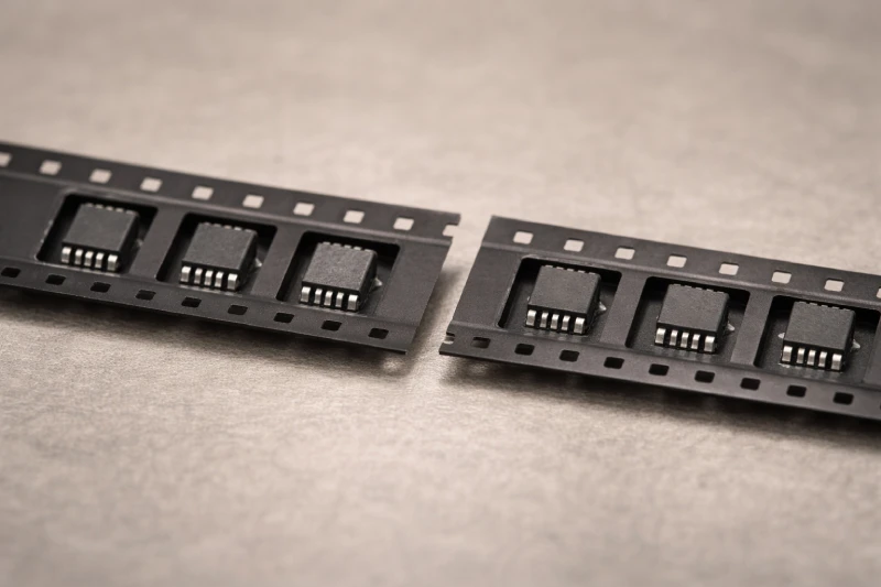
How Do Pocket Dimensions Affect Component Stability During SMT Feeding?
Pocket dimensions determine how securely a component remains positioned from packaging to placement. Length and width control lateral movement, while pocket depth affects vertical stability. If clearance is too large, components may shift or rotate during reel transport and feeder indexing. If the pocket is too tight, insertion force can stress terminations or create resistance during pick-up.
Effective pocket design balances containment and release. High-speed SMT feeding introduces repeated mechanical motion, and even slight lateral play can result in inconsistent pick positions over time. Excessive friction between component edges and pocket walls may also interfere with smooth extraction and placement accuracy.
For components requiring precise orientation, pocket geometry must align with feeder pitch and nozzle positioning. Stability depends not only on fit, but on predictable behavior under real production conditions. Early evaluation of pocket tolerances reduces feeding defects as line speed increases.
When Is Anti-Static Carrier Tape Necessary?
Anti-static carrier tape is necessary when component sensitivity to electrostatic discharge cannot be managed by environmental grounding alone. Devices such as ICs, MOSFETs, sensors, and fine-pitch packages are more vulnerable to charge accumulation during transport and SMT feeding. In these cases, standard carrier material may not provide sufficient protection against static buildup.
Reel movement, feeder indexing, and cover tape peeling can generate localized static through friction. If the carrier material does not dissipate charge in a controlled manner, components may experience electrical stress before placement. These effects are often invisible during inspection but may reduce long-term reliability and yield stability.
Reviewing the component’s ESD classification and required protection level helps determine whether anti-static or dissipative material is appropriate. Selecting the correct material early in the packaging design stage reduces downstream risk and supports consistent production performance.
Should You Choose Standard Carrier Tape or Custom Design?
Standard carrier tape is appropriate when component dimensions align with established industry widths and pocket formats. For common chip components or widely used IC packages, standardized pocket structures often provide sufficient stability without additional tooling. In these situations, verifying pocket tolerance and feeder compatibility is usually enough to maintain consistent SMT feeding performance across production batches.
Custom carrier tape becomes necessary when component geometry does not match standard pocket profiles. Irregular shapes, unusual height ratios, or sensitive surface features may require adjusted wall angles, reinforced bases, or modified cavity depth. Custom design is also considered when strict orientation control is required to prevent rotation during indexing.
The decision should balance technical requirements with expected production volume. For high-volume programs, a custom design can improve stability and reduce recurring defects. For short runs or prototype stages, validated standard formats may provide a practical and cost-efficient alternative while maintaining acceptable reliability.
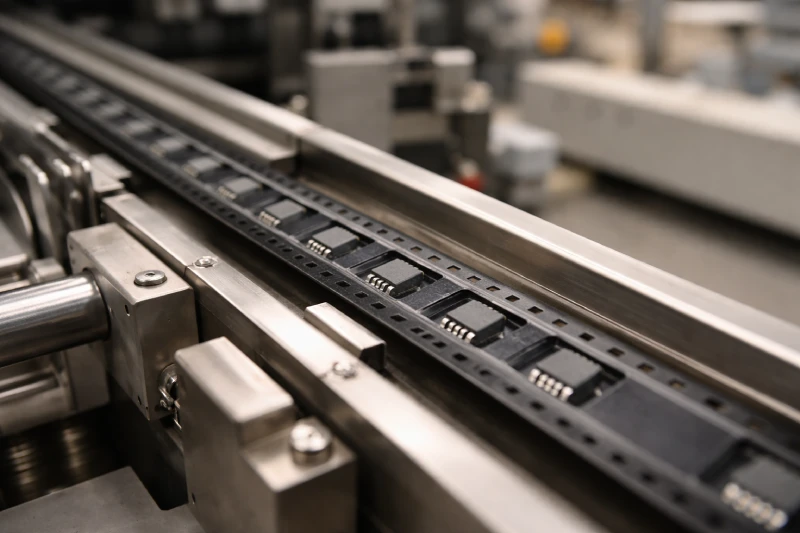
How Does SMT Line Speed Influence Tape Material and Structure?
SMT line speed influences how carrier tape performs under repeated mechanical motion. At lower speeds, minor pocket variation or material flexibility may not create immediate issues. As placement rates increase, indexing acceleration and vibration place greater stress on pocket geometry and tape rigidity, making small dimensional inconsistencies more impactful over extended production cycles.
Material stiffness is critical in maintaining pocket shape under tension. Softer materials may deform during feeder engagement, while higher-rigidity materials provide more consistent structural support. At elevated speeds, insufficient rigidity can cause subtle pocket distortion that affects component positioning before vacuum pick-up.
Line speed also affects release behavior. As cycle time decreases, the balance between containment and smooth extraction becomes more important. Evaluating tape material and structure against actual production speed improves feeding consistency and long-term process stability.
What Common Selection Mistakes Lead to Feeding or Pick-and-Place Issues?
A common mistake is allowing excessive pocket clearance to simplify insertion. Loose pockets may reduce loading resistance but increase lateral movement during reel transport and feeder indexing. This movement can lead to component rotation, leaning, or inconsistent pick position, particularly at higher SMT speeds where vibration effects are amplified.
Another issue is overlooking cover tape compatibility. Mismatch between carrier and cover tape materials can alter peel force stability, causing abrupt release or delayed separation that interferes with vacuum pick timing and placement consistency.
Tape thickness and reel tension are also underestimated. Insufficient rigidity may cause slight deformation during feeding, while uneven winding tension can disrupt indexing smoothness. These problems often emerge only after extended production runs rather than during short validation tests.
How to Validate Your Carrier Tape Before Mass Production?
Before mass production, carrier tape should be validated under actual operating conditions rather than relying only on dimensional inspection. Initial evaluation includes confirming pocket fit, orientation control, and cover tape sealing consistency. Components should be tested through real feeder systems to assess behavior during indexing and pick-up.
A pilot SMT run provides more reliable insight. Monitoring peel force stability, pick accuracy, and indexing smoothness at intended line speed helps identify issues that static checks may miss. Performance over extended cycles is more meaningful than short-duration trials.
Documenting mispick rate and orientation consistency verifies whether the selected structure and material meet long-term production requirements, reducing the risk of unexpected downtime after launch.