
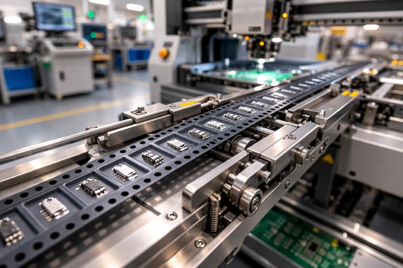
In high-speed SMT production, placement stability is typically evaluated through machine capability, feeder accuracy, and component packaging consistency. While most troubleshooting efforts focus on calibration or nozzle performance, the influence of carrier tape is often underestimated. In reality, the tape functions as the mechanical interface between component packaging and automated placement. Any dimensional deviation, material instability, or static behavior directly interacts with the feeder indexing system and pick head timing.
Unlike machine calibration errors, which tend to produce predictable patterns, carrier tape–related instability often appears intermittent: occasional mis-picks, slight placement offsets, inconsistent vacuum release, or sporadic feeder alarms. These symptoms are frequently misattributed to equipment wear or operator setup.
This article examines how carrier tape performance influences SMT stability from six engineering perspectives: feeder indexing interaction, pocket geometry behavior, material and static properties, cover tape peeling consistency, dimensional tolerances, and systematic defect identification. Understanding these mechanisms allows engineers to determine when packaging—not equipment—is the root cause.
How Does Carrier Tape Interact with SMT Feeder Indexing Systems?
SMT feeders rely on sprocket holes as mechanical indexing references. Every advancement cycle depends on consistent pitch spacing and accurate hole positioning. Even small cumulative pitch deviations can translate into component pickup misalignment over long runs.
For example, a minor pitch variation that remains within nominal tolerance may still cause amplified positional drift at high placement speeds. High-speed lines operating with fine-pitch components (0402, 0201) have minimal tolerance margin. As indexing frequency increases, dynamic errors compound, reducing placement repeatability.
Engineers should evaluate:
- Consistency of sprocket hole-to-pocket center alignment
- Cumulative pitch variation over extended tape lengths
- Machine speed versus tape dimensional stability
If feeder adjustments temporarily improve performance but instability returns with different tape lots, the issue may not be mechanical calibration. Reviewing carrier tape dimensional precision becomes essential before recalibrating equipment.
Why Pocket Geometry Determines Pick Accuracy at High Speed?
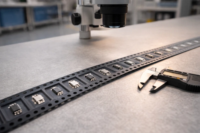
Pocket geometry directly controls how a component sits prior to pickup. Even when nominal dimensions meet specification, micro-level differences in lateral clearance, bottom flatness, or pocket wall angle influence component orientation under vibration.
Excessive lateral clearance allows micro-rotation. Insufficient depth may expose component edges, causing nozzle misalignment. Conversely, overly deep pockets may reduce vacuum efficiency due to increased air volume beneath the component.
At high indexing speeds, feeder vibration can induce slight component movement. In compact components such as 0603 or smaller, even minimal angular shift affects pickup success rate. This becomes more pronounced when handling lightweight or asymmetric devices.
Engineers should analyze:
- Pocket center alignment relative to sprocket reference
- Clearance ratio between component body and cavity
- Pocket depth consistency across the reel
In many cases, optimized embossed carrier tape geometry improves stability more effectively than further machine parameter tuning.
When Do Static and Material Properties Start Affecting Component Release?
Material behavior plays a crucial role in both component retention and release. Common carrier tape materials such as PS, PET, and PC exhibit different rigidity, static dissipation characteristics, and surface energy properties.
In dry environments or high-speed lines, insufficient static control may cause components to adhere to pocket surfaces or delay release from the nozzle. Sensitive ICs, LEDs, and CMOS devices are particularly affected.
Symptoms of static-related instability include:
- Component sticking inside pockets
- Delayed drop during placement
- Inconsistent pickup force requirement
Surface resistivity must fall within a controlled range to balance retention and release. If issues vary by environmental humidity or appear more frequently with specific device types, anti-static carrier tape should be evaluated as part of the solution.
Material choice should align with component sensitivity and production speed, rather than solely dimensional requirements.
How Does Cover Tape Peeling Behavior Impact Machine Downtime?
Cover tape peeling is synchronized with feeder advancement. Inconsistent peel force introduces mechanical fluctuation into the feeding process, potentially triggering machine alarms or minor indexing interruptions.
If peel force varies excessively, feeder tension control systems must compensate dynamically. This can affect indexing accuracy and pickup timing.
Engineers should observe:
- Peel angle stability
- Uniformity of peel force across the reel
- Presence of adhesive residue or particulate debris
Peel-generated dust may accumulate near pickup points, affecting optical recognition or vacuum performance over time. When feeder alarms appear without dimensional inconsistencies, peeling behavior often warrants inspection.
Stable peel characteristics reduce micro-disruptions that accumulate into measurable downtime.
What Tolerance Deviations Cause Mis-Pick or No-Pick Errors?
Dimensional tolerance stacking is frequently misunderstood. Individual parameters may fall within acceptable ranges, yet combined deviations produce functional instability.
Critical parameters include:
- Pitch consistency
- Sprocket hole position relative to pocket center
- Pocket depth uniformity
- Cavity symmetry
In high-speed SMT lines, acceptable tolerance windows narrow significantly. A minor deviation that poses no issue at moderate speed can cause repeated no-pick errors under rapid cycling.
Engineers should differentiate between:
- Random statistical defects (spread across batches)
- Structural deviation patterns (consistent misalignment direction)
Systematic placement drift often indicates dimensional relationship imbalance rather than feeder malfunction.
Understanding tolerance stacking effects prevents unnecessary machine recalibration cycles.
How to Identify If Placement Defects Are Caused by Tape Instead of Machine Calibration?
Distinguishing packaging-induced instability from equipment misalignment requires structured comparison testing.
Recommended approach:
- Run identical feeder settings with different tape batches
- Monitor defect repeatability pattern
- Compare placement deviation directionality
If defects remain consistent regardless of tape lot, machine calibration is likely the primary factor. However, if instability appears only with specific batches, packaging variability becomes the more probable cause.
Another indicator is defect symmetry. Machine calibration errors typically produce directional bias. Tape-related geometry issues often result in random angular shifts or intermittent no-pick events.
For components with unique shapes, thin profiles, or tight cavity clearance, standard specifications may not sufficiently stabilize positioning. In such cases, evaluating custom carrier tape geometry tailored to component structure can significantly improve consistency without altering machine configuration.
When Should You Upgrade from Standard to Custom Carrier Tape?
Standard carrier tape solutions perform reliably for most applications. However, process stability may degrade under certain conditions:
- Extremely thin or asymmetrical components
- Ultra-high-speed placement environments
- Tight clearance designs with minimal tolerance margin
- Yield-sensitive production where minor instability impacts throughput
When recurring placement variability cannot be resolved through feeder calibration or environmental control, packaging geometry optimization becomes the logical next step.
Custom carrier tape design allows refinement of cavity dimensions, retention balance, and indexing alignment to match specific component structures. For high-value or precision applications, packaging optimization often delivers more consistent long-term stability than repeated mechanical adjustments.
Final Perspective
SMT placement stability is not determined solely by machine capability. Carrier tape functions as a dynamic mechanical system interacting continuously with feeder indexing and pick head motion.
Understanding how pitch precision, pocket geometry, material behavior, peel consistency, and tolerance stacking influence performance enables engineers to diagnose issues more accurately. By evaluating packaging variables alongside equipment parameters, production teams can reduce unnecessary recalibration, minimize downtime, and improve overall yield stability.
In advanced SMT environments, packaging should not be viewed as passive containment—but as an active contributor to process performance.