Precision Carrier Tape Packaging Solutions from China

Custom Embossed Carrier Tape for Specialized SMT Components

Custom Embossed Carrier Tape is developed for electronic components that cannot be reliably packaged using standard EIA-481 formats, due to non-standard geometry, pocket depth, pitch, or handling requirements.

This page is intended for component manufacturers and SMT assembly teams working on project-based packaging development, where carrier tape design, sampling, and validation must be engineered around the component and its automated pick-and-place process rather than selected from predefined specifications.

  • Components that do not fit standard carrier tape pocket sizes or pitches
  • Irregular, asymmetric, or fragile parts requiring custom pocket geometry
  • Deep, shallow, or stepped pocket designs beyond standard tooling limits
  • Orientation or retention issues affecting feeding accuracy
  • Project-based packaging for new or evolving component designs
  • Share:

When a Custom Embossed Carrier Tape Is Required

A custom embossed carrier tape becomes necessary when standard carrier tape solutions fail to meet functional requirements during actual handling, feeding, or production use.

  • Standard carrier tape cannot maintain component orientation during feeding
  • Excessive component movement leads to mis-picks or placement errors
  • Pocket depth or structure causes component damage, deformation, or jamming
  • Feeding interruptions occur despite correct machine setup and parameters
  • Repeated adjustments fail to resolve stability or retention issues
  • No existing standard pocket design passes internal or customer validation
Pick-and-place feeding failure caused by non-standard electronic component in standard embossed carrier tape pocket

Non-Standard Packaging Challenges

Custom Embossed carrier tape development typically involves multiple interrelated challenges. These challenges must be analyzed at the pocket design and tooling level to ensure stable handling throughout the SMT process.

  • Component Geometry & Support Mechanics

    • Non-uniform contact surfaces preventing stable bottom support
    • Limited flat reference areas for consistent seating
    • Asymmetric mass distribution affecting balance inside the pocket
    • Sensitive edges or terminals requiring controlled wall contact
  • Pocket Depth, Wall Structure & Clearance Control

    • Depth mismatches causing floating, rocking, or compression

    • Vertical clearance affecting component release during pick-up

    • Pocket wall angles influencing component centering behavior

    • Risk of deformation due to insufficient sidewall support

  • Pitch, Indexing & Feeding Alignment Constraints

    • Non-standard pitch requirements incompatible with standard tooling

    • Index hole alignment tolerance affecting feed accuracy

    • Pocket-to-pocket spacing impacting pick position repeatability

    • Accumulated tolerance issues across long feeding cycles

  • Retention, Release & Handling Stability

    • Retention force imbalance causing either component loss or sticking

    • Pocket geometry interfering with vacuum nozzle access

    • Release inconsistency during high-speed pick-and-place

    • Sensitivity to vibration during transportation or reel winding

  • Tooling & Manufacturing Feasibility Constraints

    • Tooling limitations affecting achievable pocket geometry

    • Material forming behavior influencing wall definition and repeatability

    • Mold complexity versus dimensional consistency trade-offs

    • Scalability risks between prototype tooling and mass production

Custom Design & Tooling Process

  • Requirement Clarification & Risk Identification

    Component geometry, orientation, and handling intent are reviewed to establish a unified technical baseline. Functional risks and acceptance criteria are defined early to align design objectives with actual SMT process requirements.

  • Pocket Design & Structural Definition

    Pocket geometry is developed around component support, positioning, and release behavior. Depth, wall structure, and clearances are defined while considering nozzle access and basic manufacturability constraints.

  • Tooling Strategy & Mold Feasibility Planning

    Tooling approach and mold structure are planned based on pocket complexity and forming behavior. Design decisions are aligned with dimensional repeatability and intended production scale.

  • Prototype Tooling & Sample Production

    Prototype tooling is used to produce initial samples for physical evaluation. Actual components are loaded to verify fit, stability, and handling behavior beyond drawing assumptions.

  • Validation Feedback & Design Refinement

    Samples are validated under simulated or actual SMT conditions to confirm feeding and pickup performance. Pocket geometry is refined as needed before final approval.

  • Tooling Freeze & Production Readiness

    Tooling dimensions and process parameters are finalized and frozen after validation. Quality reference points and inspection criteria are defined to ensure consistent volume production.

Sampling & Validation Workflow

Sampling and validation are conducted as controlled engineering checks to confirm that pocket design and tooling assumptions perform reliably under real handling and feeding conditions.
  • Prototype carrier tape samples are evaluated using actual components to verify pocket fit, orientation stability, and retention behavior under static conditions. Visual and handling-level checks are performed to identify instability, interference, or unexpected contact points that may not appear in drawings.

    Feeding and pickup performance are then assessed under simulated or actual SMT conditions to confirm nozzle access, pickup reliability, and release consistency. Validation focuses on functional behavior rather than cosmetic appearance, ensuring that the carrier tape performs predictably during automated operation.

    Observed deviations or performance issues are documented and reviewed before design approval. Only designs that meet predefined functional acceptance criteria proceed to tooling freeze and production readiness.

  • sampling and validation of custom carrier tape with actual electronic components in SMT test environment

Production Scalability & Lead Time Logic

  • Scalability is established only after a design is validated and tooling is stabilized. Early-stage runs are typically used to confirm repeatability and loading performance, while volume production requires locked tooling parameters, controlled material sourcing, and consistent forming conditions to maintain dimensional stability across long orders.

    Lead time follows a decision-based sequence, not a single fixed number. Time is primarily influenced by the number of design iterations required, prototype sampling cycles, validation scope (bench checks vs. feeder trials), and whether modifications are needed after feedback. Projects with clear acceptance criteria and complete input data generally move faster through sampling and approval.

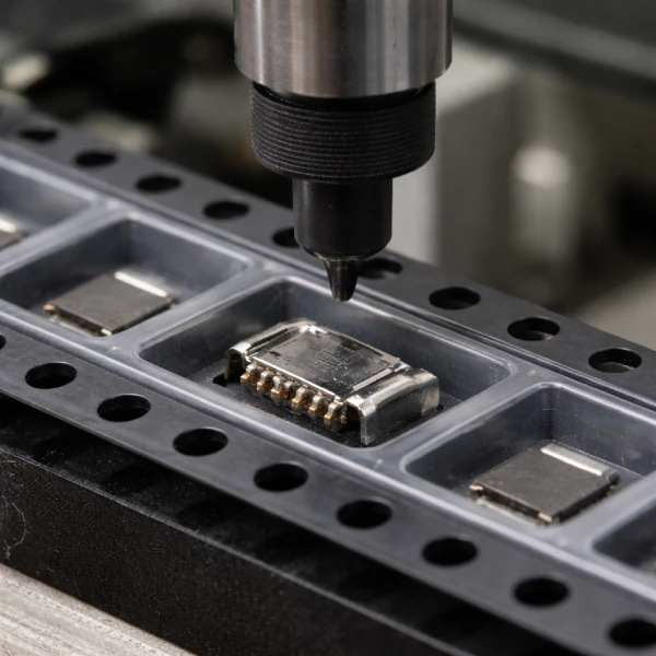
    Production readiness is confirmed through process control points. Before scaling, key references such as pocket dimensions, indexing alignment, sealing behavior with cover tape, and inspection criteria are defined so that output consistency can be maintained across multiple batches.

  • What affects lead time in custom embossed carrier tape projects

    • Design iteration scope
      Number of refinement cycles required to achieve stable component behavior in the pocket.
    • Tooling complexity
      Pocket depth, wall structure, and tolerance control affecting mold development and forming repeatability.
    • Sampling & validation method
      Bench inspection versus feeder or SMT line trials requiring different validation timelines.
    • Material selection & availability
      Standard, anti-static, or conductive material grades impacting sourcing and process stability.
    • Production ramp strategy
      Pilot runs used to confirm consistency before scaling to volume production.

Information Required From Customers

Providing complete input information helps reduce design iterations and allows feasibility evaluation to proceed efficiently.

    • Component Information

      Component drawings, dimensional data, or samples are needed to define pocket geometry and support logic.

    • Packaging & Orientation Requirements

      Preferred orientation and handling constraints determine pocket positioning, retention, and release behavior.

    • SMT Process & Feeding Environment

      Feeding setup and equipment details help assess pickup stability and validation scope.

    • Volume Expectation & Project Stage

      Estimated volumes and project stage guide tooling strategy and validation depth.

    • Material or ESD Constraints (If Applicable)

      Material or ESD requirements define process boundaries and material selection.

Request A Quote

Header Form