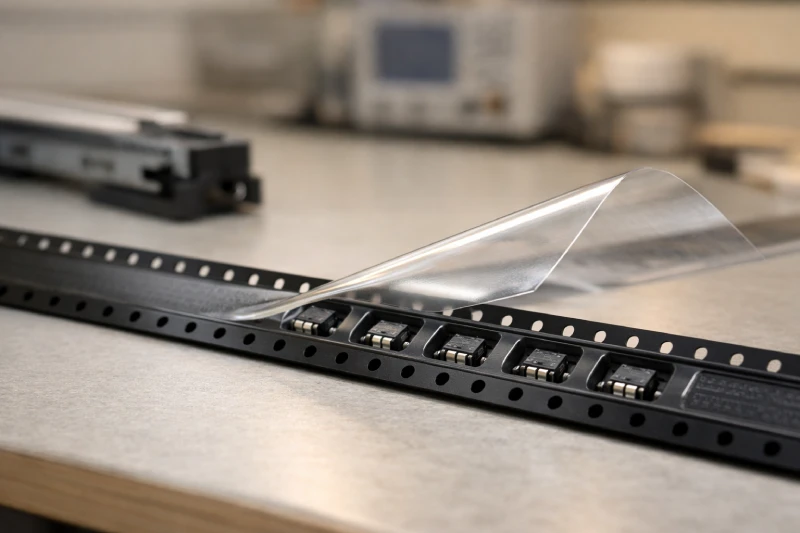
In most SMT packaging applications, carrier tape and cover tape are designed to function as a system rather than as independent materials. While it is technically possible to handle embossed carrier tape without a cover layer in controlled environments, production-level component transport almost always requires both. The real engineering question is not whether they should be used together, but whether they are properly matched.
A well-formed pocket does not guarantee component stability if the sealing layer behaves unpredictably during peeling. Likewise, a high-quality cover film cannot compensate for poor pocket geometry or material inconsistency. In high-speed SMT lines, compatibility directly affects feeding reliability, pick accuracy, ESD protection, and yield stability.
Understanding how carrier tape and cover tape interact mechanically and electrically allows engineers and sourcing teams to prevent subtle but costly production issues before they scale.
What Happens If Carrier Tape and Cover Tape Are Not Properly Matched?
Mismatch typically shows up first as feeder instability rather than obvious packaging failure. When peel strength falls outside the optimal window, the cover tape may lift too early, too late, or unevenly. This can cause micro-vibrations inside the pocket just before pick-up, leading to component rotation or slight positional drift.
If adhesion is too weak, parts may escape during reel handling or transit. If it is too strong, sudden release forces at the peel point can disturb lightweight components, especially 0201 and 01005 packages. In high-speed feeders, even minor peel inconsistency amplifies over thousands of placements per hour.
Improper matching can also increase static charge accumulation at the separation point. If the carrier material and cover film have different electrostatic characteristics, discharge risk increases precisely where the component is most exposed.
Most yield losses linked to tape systems are not caused by catastrophic defects—but by subtle incompatibilities that only appear under dynamic conditions.
Why Is Peel Strength More Critical Than Most Engineers Expect?
Peel strength is often treated as a simple specification number. In practice, it is a dynamic performance parameter that interacts with feeder speed, peel angle, ambient humidity, and component mass.
A peel force that performs well at low speed may become unstable at 40,000+ components per hour. As peel speed increases, adhesive behavior changes. The separation event becomes more abrupt, and energy transfer into the pocket increases. That energy can momentarily lift or shift the component before the pick head engages.
Equally important is peel consistency across reel length. Variations between inner and outer reel layers can create intermittent placement issues that are difficult to trace.
Rather than focusing only on nominal peel values, engineers should evaluate peel behavior under actual feeder conditions. Compatibility between embossed carrier tape structure and the selected cover film plays a decisive role in stabilizing this dynamic interaction.
How Do Material Differences Affect Compatibility?
Carrier tapes are commonly produced from PS, PET, or PC, each with different rigidity, surface energy, and thermal response. Cover tapes, in contrast, may use heat-activated sealing layers or pressure-sensitive adhesive systems. Compatibility depends on how these material systems interact at the sealing interface.
For example, a rigid PET carrier tape may require a cover film optimized for dimensional stability to maintain consistent seal width. A softer PS base may tolerate different adhesive behavior but could deform under excessive sealing temperature.
Surface energy differences influence bonding uniformity. If the adhesive chemistry is not matched to the carrier substrate, peel performance may vary across production batches. Environmental conditions such as humidity further complicate the interaction.
Material pairing should therefore be evaluated as a system-level decision. When developing custom carrier tape solutions, reviewing sealing compatibility early prevents downstream feeding inconsistencies.
Is Anti-Static Performance Dependent on Both Tapes or Just One?
A common misconception is that static control is achieved solely through anti-static carrier tape. In reality, electrostatic behavior is influenced by the entire packaging system—including the cover layer.
During peeling, friction between materials generates charge. If the cover tape lacks appropriate static-dissipative properties, charge may accumulate precisely at the moment of exposure. This is particularly critical for sensitive ICs and fine-pitch components.
Even when the carrier material meets dissipative standards, a non-compatible cover film can undermine system-level ESD control. Balanced surface resistivity and controlled charge decay across both materials are essential.
For applications involving high-sensitivity devices, anti-static carrier tape should always be evaluated together with compatible cover materials to ensure stable electrostatic performance throughout feeding.
When Can Carrier Tape Be Used Without Cover Tape?
There are limited situations where carrier tape may be used without a cover layer. Examples include short internal transfers between controlled processes or manual loading scenarios where components are immediately consumed.
However, these cases operate within strict environmental and handling boundaries. Without a cover layer, components are exposed to vibration, dust, and electrostatic influence. Even minimal movement can affect coplanarity or orientation.
For any external shipment, reel storage, or automated feeding process, omitting the cover tape introduces unacceptable risk. What appears efficient in the short term may result in yield instability during production ramp-up.
In practical SMT manufacturing environments, the carrier-cover pairing remains the industry standard for reliable component containment.
How to Verify Carrier & Cover Tape Compatibility Before Mass Production?
Validation should simulate real production conditions rather than relying solely on static lab tests.
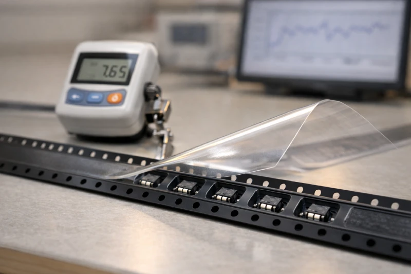
First, conduct controlled peel force measurement across different reel positions to check consistency. Second, run high-speed feeder trials at actual placement rates to observe dynamic component behavior. Monitor for micro-rotation, lift, or misalignment at the peel point.
Third, evaluate environmental stability through humidity and temperature conditioning. Adhesive systems can respond differently under elevated moisture levels. Finally, inspect pocket retention after simulated transportation vibration to ensure components remain stable before feeding.
Compatibility testing should focus on system performance—not just individual material specifications. Early validation reduces troubleshooting time once mass production begins and protects placement yield under real operating conditions.
Should You Source Carrier Tape and Cover Tape from the Same Supplier?
From a risk-management perspective, sourcing both materials as an integrated system simplifies accountability and consistency control. When carrier and cover tapes are developed and tested together, peel behavior and sealing compatibility are typically more predictable.
If sourced separately, variation between suppliers may introduce subtle interface differences. When issues arise, determining root cause becomes more complex.
That said, dual sourcing strategies can still work if compatibility testing is rigorous and ongoing. The key is to treat carrier and cover tape as a coordinated engineering system rather than interchangeable commodities.
In high-reliability SMT environments, stability at the packaging interface often determines stability on the production line.