Introduction
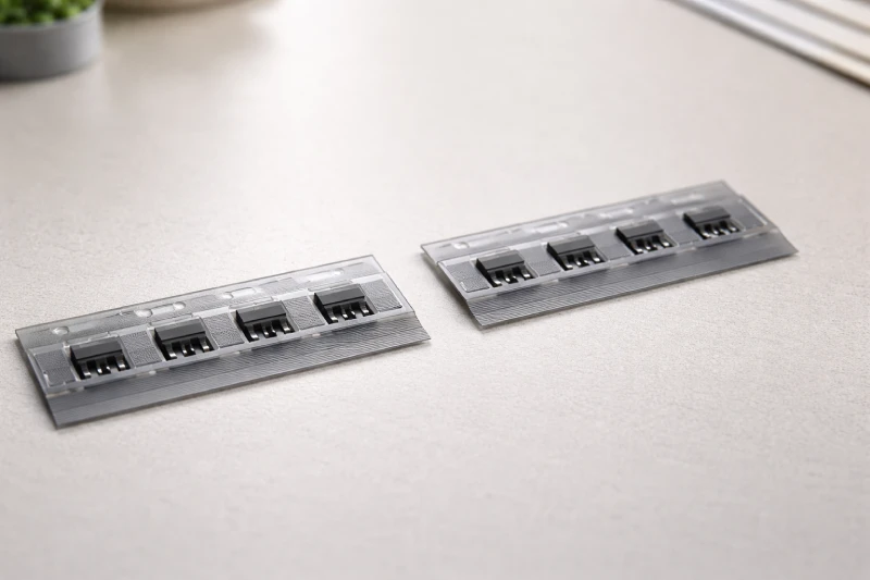
In electronic component packaging, carrier tape is often treated as a standard consumable — selected by size, ordered by spec, and rarely questioned unless a failure occurs. However, in high-volume SMT production, carrier tape is not just packaging. It becomes part of the feeding system, part of the positioning mechanism, and indirectly, part of the yield equation.
Many surface-mount issues that appear to be machine-related — component misalignment, pick failure, rotation, or intermittent feeding stops — can trace back to how the component is seated, supported, and protected inside the tape pocket. Transportation vibration, reel tension, and electrostatic exposure further compound these risks before the component even reaches the placement head.
Understanding why carrier tape design matters is not about comparing products. It is about recognizing when packaging becomes a process variable — and how that variable influences stability, reliability, and production consistency.
What Problems Occur When Carrier Tape Is Poorly Designed?
When carrier tape design does not properly match the component geometry, instability usually appears long before a root cause is identified. The most common symptoms are not dramatic failures — they are small, repeatable inconsistencies that accumulate over time.
One frequent issue is component rotation or tilt inside the pocket. If pocket depth, wall angle, or support surface is not optimized, the component may shift during reel winding, transportation, or feeder advancement. Even minor angular deviation can increase pick correction time or reduce placement accuracy.
Another problem is inconsistent pocket forming. Variations in pocket dimensions or pitch can lead to intermittent feeding interruptions. The feeder may advance unevenly, causing tension fluctuations that result in mis-picks or occasional jams. These interruptions often appear random but originate from dimensional inconsistency in the tape structure.
Deformation is also a hidden risk. If material stiffness is insufficient, pocket walls may flex under stacking pressure or reel tension. This compromises component seating stability before the reel ever reaches the production line.
In many cases, the SMT machine is adjusted repeatedly to compensate for what is actually a packaging stability issue. Recognizing these patterns early allows engineers to evaluate whether the carrier tape structure — not the equipment — is the underlying variable affecting performance.
How Does Carrier Tape Affect Pick-and-Place Accuracy?
Pick-and-place systems rely on repeatability. Every advance of the feeder, every indexing movement, and every suction event assumes that the component is presented in a predictable position. Carrier tape plays a direct role in maintaining that positional consistency.
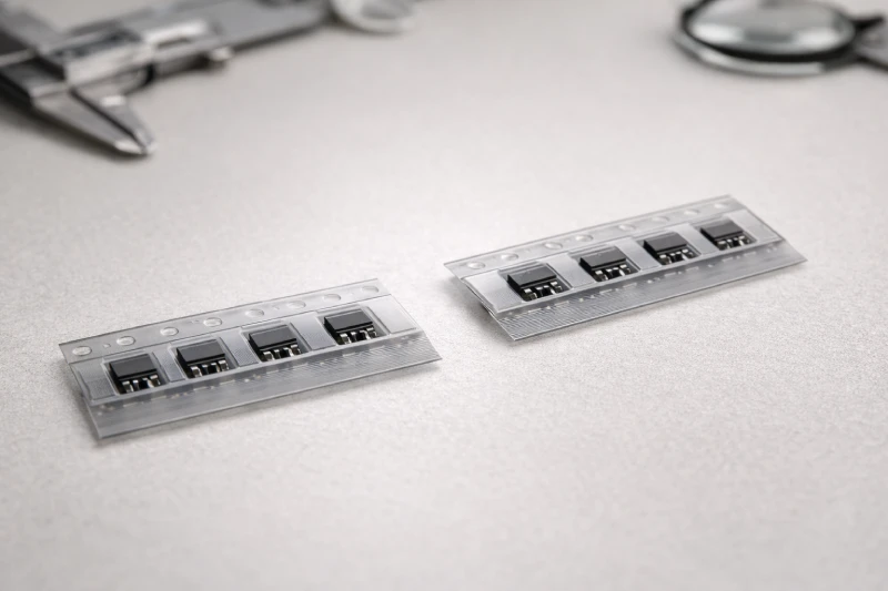
Pocket geometry determines how the component sits before pickup. If pocket depth is too shallow, the component may sit proud and shift under vibration. If too deep, the nozzle may require additional correction or fail to achieve stable suction. Even slight inconsistencies in pocket floor flatness can affect how uniformly the component rests, especially for thin or asymmetrical parts.
Pitch consistency is another critical factor. The feeder advances based on standardized pitch intervals. If pocket spacing varies beyond tolerance, alignment between the pickup nozzle and component centerline can drift incrementally. This drift may not cause immediate failure, but it reduces placement margin and increases reliance on vision correction.
Component seating stability also influences suction reliability. When a component tilts within the pocket, vacuum engagement may occur off-center, increasing the likelihood of rotation during lift. Over thousands of cycles, this small instability can translate into measurable placement variation.
In high-speed SMT environments, placement accuracy is not determined solely by machine capability. It depends equally on how consistently the component is presented — and that consistency begins with carrier tape structure.
Why Is ESD Protection Often Underestimated?
Electrostatic discharge risk in electronic component packaging is often evaluated at the device level, but less attention is given to how the carrier tape contributes to charge accumulation and dissipation. During reel winding, transportation, storage, and feeder advancement, repeated friction and separation events generate static. If the tape material does not maintain controlled surface resistivity, charge can accumulate along the pocket walls and cover interface.
Unlike immediate mechanical defects, ESD-related damage is frequently latent. A component may pass visual inspection and initial electrical testing, yet experience long-term reliability degradation due to microscopic discharge events. These failures are difficult to trace back to packaging because the damage mechanism leaves minimal visible evidence.
Another overlooked factor is resistivity mismatch between carrier tape and cover tape. If one layer dissipates charge faster than the other, localized potential differences can form during peeling at the feeder. The moment of cover tape removal is particularly sensitive, as rapid separation can generate discharge near exposed leads or pads.
In environments handling fine-pitch ICs, sensors, or high-value semiconductor devices, carrier tape is not simply a containment medium. It becomes part of the ESD control strategy. Evaluating its electrical characteristics under real handling conditions is therefore a stability consideration, not just a compliance checkbox.
When Is Standard Carrier Tape Not Enough?
Standard carrier tape works well when component geometry is simple, weight distribution is balanced, and dimensional tolerances fall within common ranges. However, not all electronic components behave predictably under movement and vibration. Certain design characteristics introduce instability that standard pocket structures may not adequately control.
Ultra-thin devices, for example, are more susceptible to tilt if pocket floor flatness or sidewall support is insufficient. Components with asymmetrical shapes or uneven mass distribution may rotate inside generic cavities during transportation or feeder indexing. Heavy or tall components can also exert higher lateral force against pocket walls, increasing the risk of deformation or micro-shift.
Another scenario involves high-value or sensitive ICs where even minor positional instability increases risk exposure. In such cases, reducing movement margin inside the pocket becomes more critical than maintaining broad compatibility across part families.
Engineers typically recognize the limitation of standard tape only after encountering inconsistent feeding behavior or subtle placement variation. A more proactive approach is to evaluate whether the component’s geometry, thickness tolerance, and center-of-gravity characteristics justify a pocket design tailored to its specific mechanical profile.
How Does Carrier Tape Impact Transportation Stability?
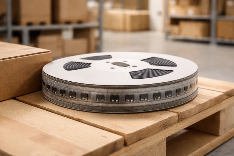
Before a component reaches the SMT line, it may experience multiple stages of handling — reel winding, carton stacking, long-distance transportation, and warehouse storage. During these stages, carrier tape becomes the primary mechanical restraint system protecting each device from movement.
Vibration is one of the most influential variables. Continuous low-amplitude vibration during shipping can gradually cause micro-shift inside the pocket if sidewall support is insufficient. While the displacement may be small, repeated motion increases the likelihood of rotation or misalignment before feeder loading.
Reel tension also plays a role. Excessive winding force can introduce compressive stress on pocket walls, especially if material rigidity is marginal. Over time, this may slightly alter cavity shape or reduce retention stability. Conversely, insufficient tension can allow internal movement within the reel layers.
Stacking pressure during bulk packaging further compounds these forces. When cartons are palletized, vertical load can transfer through reel flanges and indirectly affect pocket structure. If the tape lacks adequate structural integrity, deformation may occur before the reel is even opened.
Transportation-related instability often manifests later as feeding inconsistency. Understanding this link helps engineers evaluate carrier tape not only for line performance, but for supply chain resilience.
Can Carrier Tape Influence Overall Yield?
Carrier tape does not directly assemble components, yet it quietly affects multiple variables that determine overall manufacturing yield. When presentation stability is inconsistent, even small positional deviations can increase reliance on machine correction systems. Over time, this reduces process margin.
A single mis-pick may seem insignificant. However, if pocket geometry allows minor rotation or tilt, correction cycles increase. These micro-adjustments extend placement time, introduce variability, and occasionally result in dropped or rejected components. Across high-volume production, these small inefficiencies accumulate.
Intermittent feeding interruptions also contribute to yield impact. Each pause or manual intervention disrupts process flow and increases the chance of handling error. While the root cause may originate in pocket design or dimensional tolerance, the visible symptom appears as line instability.
Latent ESD exposure adds another layer of risk. Failures that occur post-assembly may be difficult to attribute to packaging conditions, yet packaging stability directly affects how components are protected before soldering.
From a cost perspective, carrier tape influences scrap rate, rework frequency, and process consistency. Yield is not only a function of machine capability; it is also shaped by how reliably each component is presented to the placement system.
How Should Engineers Evaluate Carrier Tape Before Mass Production?
Carrier tape evaluation should occur before full-scale production, not after instability appears on the line. A structured validation approach helps determine whether the tape functions as a stable presentation system rather than simply a dimensional match.
Initial assessment typically begins with pilot feeding tests. Engineers observe indexing smoothness, pocket alignment consistency, and pickup repeatability across extended cycles. The goal is not only to confirm compatibility, but to detect subtle variations in seating behavior under continuous operation.
Vibration simulation or controlled transport testing can further reveal whether components shift within the pocket after handling. Comparing pre- and post-test positioning provides insight into retention stability under real-world logistics conditions.
Material performance should also be reviewed. Mechanical rigidity, dimensional tolerance stability, and electrical characteristics such as surface resistivity need to align with the sensitivity level of the component. Peeling behavior during cover tape removal is another critical observation point, as sudden discharge or abrupt separation can introduce risk.
By validating carrier tape under simulated production and transport conditions, engineers reduce the likelihood of discovering instability during mass assembly. Evaluation at this stage ensures that packaging remains a controlled variable rather than an unpredictable influence on process stability.