Carrier tape packaging is widely used in modern electronics manufacturing to support automated SMT assembly. By organizing electronic components in a continuous tape format, carrier tape enables reliable feeding into high-speed pick-and-place machines, improving production efficiency and consistency. For many SMT production lines, tape-and-reel packaging has become the standard method for transporting and feeding small electronic components.
However, not every electronic component is suitable for carrier tape packaging. The compatibility between a component and carrier tape depends on several factors, including component size, geometry, weight, and stability during automated feeding. If these factors are not properly evaluated, issues such as component rotation, mis-pick errors, or lead damage may occur during assembly.
For packaging engineers and SMT process specialists, understanding which components work best with carrier tape—and how to evaluate compatibility—is essential for ensuring stable production and minimizing assembly risks.
Why Not All Electronic Components Are Suitable for Carrier Tape
Carrier tape packaging is specifically designed to support automated SMT assembly processes. Its structure—consisting of formed pockets, cover tape sealing, and standardized indexing holes—allows components to be fed consistently into pick-and-place equipment. However, this packaging method works best only when the component design and physical characteristics align with the limitations of the tape structure.
Some electronic components are simply not well suited for carrier tape. Extremely large components may exceed the available pocket size or require deeper cavities than standard tape formats allow. Similarly, heavy mechanical parts may not remain stable within the pocket during transportation or feeder movement. Fragile optical components or highly sensitive devices may also require more protective packaging formats such as trays.
Irregularly shaped components can present additional challenges. If the geometry of a component prevents stable positioning inside the pocket, the component may rotate or tilt during tape feeding. This instability can lead to pick-and-place errors or even damage to the component leads.
For these reasons, packaging engineers typically evaluate the relationship between component structure and packaging method early in the design process. Selecting the appropriate packaging format ensures both transportation protection and reliable automated assembly.
What Types of Electronic Components Are Commonly Packaged in Carrier Tape
Many electronic components are naturally compatible with carrier tape packaging, particularly those designed for automated SMT assembly. These components typically have standardized dimensions, stable geometries, and production volumes that justify automated feeding.
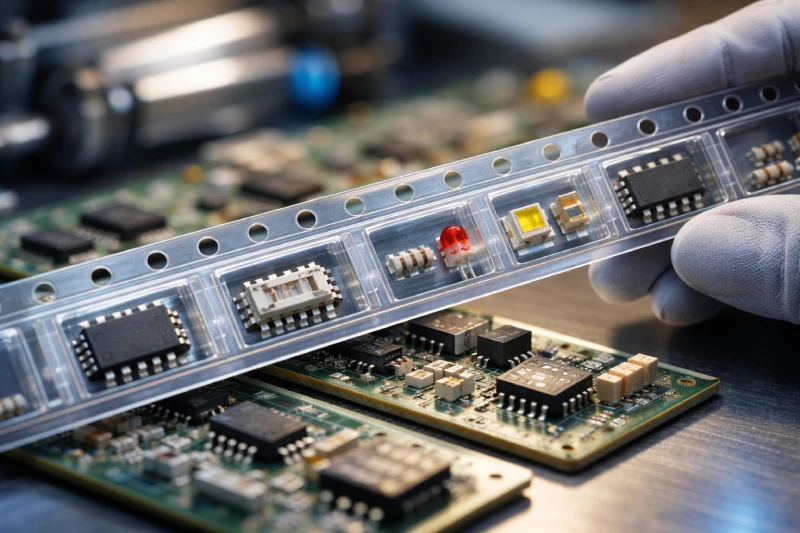
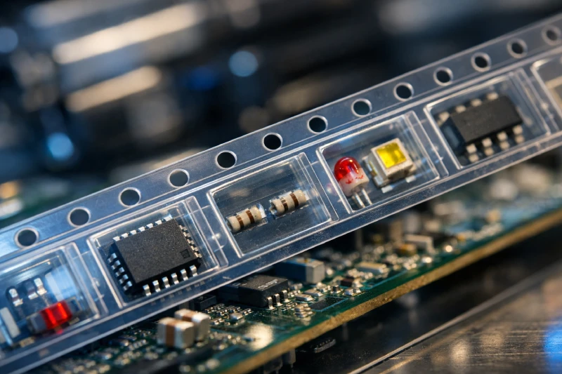
Common electronic components packaged in carrier tape include:
- Integrated circuits such as QFN, BGA, QFP, and SOP packages
- Passive components including resistors, capacitors, and inductors
- Light-emitting diodes (LEDs)
- Small sensors and MEMS devices
- RF components and communication modules
- Discrete semiconductors such as diodes and transistors
These components are generally compact, lightweight, and manufactured in large quantities. Their dimensions are predictable, making them suitable for standardized pocket designs in embossed carrier tape.
In addition, these components are commonly assembled using high-speed pick-and-place machines, which require stable feeding systems. Carrier tape packaging supports this requirement by ensuring consistent spacing, orientation, and positioning of components throughout the assembly process.
As a result, carrier tape has become one of the most widely adopted packaging formats in electronics manufacturing for small to medium-sized SMT components.
How Component Size and Geometry Affect Carrier Tape Compatibility
Component size and geometry are among the most critical factors when determining whether a component can be packaged in carrier tape. The pocket structure inside the tape must be designed to securely hold the component while still allowing reliable removal during the pick-and-place process.
The first consideration is the overall component dimension, including length, width, and height. The pocket must provide enough clearance for the component to fit without excessive movement. If the pocket is too tight, the component may become stuck or difficult to pick. If the pocket is too loose, the component may shift during transportation or feeding.
Pocket clearance is carefully controlled to balance stability and accessibility. In many cases, engineers design pockets with a small margin between the component and the cavity walls. This margin prevents friction while still maintaining positional stability.
Lead protection is another important factor. Components such as connectors or packages with exposed leads require pocket designs that prevent mechanical stress on the pins. Improper pocket design may bend leads or damage delicate contact structures.
Finally, the center of gravity of the component also influences stability. Components with uneven weight distribution may rotate or flip inside the pocket if the cavity design does not properly support them. Ensuring proper orientation within the pocket is essential for reliable SMT placement.
When Custom Carrier Tape Is Required for Special Components
While many components can use standardized carrier tape formats, some devices require custom carrier tape designs. This is particularly true for components with unique geometries, delicate structures, or specialized packaging requirements.
Custom carrier tape is commonly used for components such as connectors, optical modules, advanced sensors, and certain semiconductor packages. These components may have irregular shapes that do not fit standard pocket designs, or they may require additional support to prevent movement during transportation.
For example, optical components often need precise orientation control to avoid damage to sensitive surfaces. Similarly, Mini LED devices and wafer-level packages may require shallow but precisely shaped pockets to maintain stability.
Custom pocket designs allow engineers to adjust pocket depth, cavity geometry, and component orientation. These adjustments help ensure that the component remains stable during handling, shipping, and automated feeding.
By tailoring the pocket structure to the specific component, custom carrier tape solutions can significantly improve packaging reliability and reduce assembly risks.
How to Evaluate Component Stability During SMT Feeding
Even if a component physically fits inside a carrier tape pocket, its behavior during SMT feeding must still be evaluated. Stable feeding is critical for high-speed assembly lines, where pick-and-place machines may operate at extremely high placement rates.
One key factor affecting stability is pocket tolerance. The relationship between the component dimensions and the cavity size determines whether the component remains securely positioned during tape movement. Proper tolerance prevents both excessive movement and mechanical interference.
Cover tape peel force also plays an important role. When the cover tape is removed during feeding, the peel force must be balanced carefully. If the peel force is too high, it may pull components upward. If it is too low, components may move or escape from the pocket prematurely.
Feeder vibration is another consideration. During high-speed operation, tape feeders can generate small vibrations that affect component stability. If the pocket design does not adequately support the component, these vibrations may cause the component to rotate or shift position.
Orientation control is equally important. The pocket must ensure that components maintain a consistent orientation so that the pick-and-place machine can correctly identify and place them. Poor orientation control can lead to placement errors and production interruptions.
Carrier Tape vs Tray vs Tube: How to Choose the Right Packaging Method
Carrier tape is only one of several packaging methods used in electronics manufacturing. In some cases, tray or tube packaging may be more suitable depending on the characteristics of the component.
Carrier tape packaging is typically preferred for high-volume SMT assembly. Its continuous format allows components to be fed directly into automated pick-and-place machines, enabling efficient production and minimal manual handling.
Tray packaging is often used for larger or more fragile components, particularly advanced semiconductor devices. Trays provide individual compartments that offer better protection for sensitive components during transportation.
Tube packaging is commonly used for medium-volume semiconductor components. Tubes are cost-effective and relatively simple but may require manual loading into feeders before assembly.
Selecting the appropriate packaging method requires evaluating production volume, component sensitivity, and assembly requirements. For many high-volume SMT components, carrier tape remains the most efficient solution.
Key Questions Engineers Should Ask Before Selecting Carrier Tape Packaging
Before selecting carrier tape packaging, engineers typically evaluate several practical factors to ensure compatibility between the component and the packaging system.
First, it is important to determine whether the component is designed for automated SMT assembly. Components intended for manual assembly or specialized handling may not benefit from carrier tape packaging.
Next, engineers review whether the component dimensions are compatible with available pocket designs. Accurate dimensional analysis helps ensure that the component will remain stable during transportation and feeding.
Another key consideration is electrostatic protection. Certain semiconductor devices require anti-static packaging materials to prevent electrostatic discharge during handling.
Engineers must also evaluate whether the component will remain stable during high-speed feeder operation. Testing or simulation may be required to confirm reliable feeding performance.
Finally, some components may require customized pocket designs to maintain proper orientation and protection. Addressing these factors early in the packaging design process helps prevent feeding errors, component damage, and production downtime in SMT assembly environments.