
Surface-mount device (SMD) carrier tape plays a critical role in modern SMT manufacturing and electronic component packaging. Designed to securely hold small electronic components in precisely formed pockets, carrier tape enables automated handling, transportation, and feeding into high-speed pick-and-place machines. Without this packaging method, reliable large-scale SMT assembly would be extremely difficult.
In tape & reel packaging systems, carrier tape works together with cover tape and reels to create a continuous packaging format that protects components from damage, contamination, and misalignment during shipping and automated assembly. Because SMT production relies heavily on speed, accuracy, and consistency, the design and quality of carrier tape directly affect production efficiency.
This guide explains what SMD carrier tape is, how it works, the materials and standards involved, and how to choose the right carrier tape design for different electronic components and SMT production environments.
What Is SMD Carrier Tape?
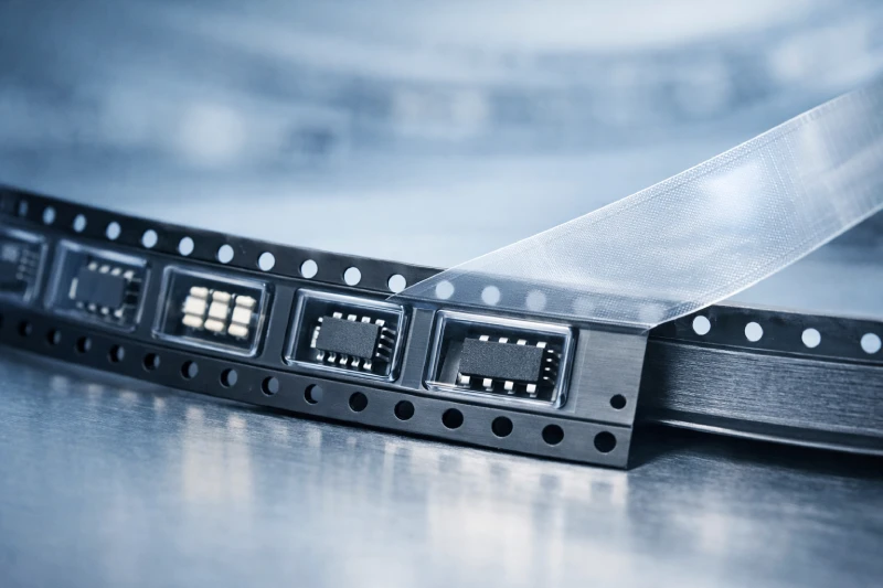
SMD carrier tape is a specially designed plastic packaging tape used to store, transport, and automatically feed surface-mount components during SMT assembly. The tape contains a series of precisely formed pockets that hold individual components in a fixed orientation, allowing pick-and-place machines to reliably pick each part during high-speed production.
Simple Definition
In simple terms, SMD carrier tape is a pocketed plastic tape that organizes and protects surface-mount components for automated SMT placement machines. Each pocket is engineered to match the dimensions of the component, ensuring stable positioning and consistent feeding throughout the assembly process.
What Components Use Carrier Tape
Carrier tape is widely used to package many types of surface-mount electronic components, such as:
- Integrated circuits (ICs)
- Resistors
- Capacitors
- LEDs
- Connectors
- Sensors
- Small semiconductor devices
These parts are typically small and sensitive to movement, making pocketed tape packaging an effective solution for maintaining proper orientation and protection.
Why SMT Production Requires Carrier Tape
SMT production relies on automated equipment operating at high speeds. Carrier tape supports this process by providing a standardized method for component handling. Key benefits include:
- Reliable automated feeding into pick-and-place machines
- Protection during transport and storage
- Consistent spacing and alignment for accurate placement
How SMD Carrier Tape Works in Tape & Reel Packaging
SMD carrier tape functions as a critical part of the tape & reel packaging system used throughout the electronics manufacturing industry. By organizing components into evenly spaced pockets and sealing them with cover tape, the system allows electronic parts to be safely transported and automatically supplied to SMT assembly equipment.
This standardized packaging method ensures that components remain protected, correctly oriented, and ready for automated pick-and-place operations during high-volume production.
The Basic Tape & Reel System
A typical tape & reel packaging system consists of three main elements:
- Carrier Tape – A pocketed plastic tape that holds individual components in fixed positions
- Cover Tape – A sealing film applied over the carrier tape to secure components inside the pockets
- Plastic Reel – A spool used to wind and store the carrier tape for handling and machine feeding
Together, these components create a continuous packaging format that can be easily loaded into SMT feeders.
Step-by-Step Packaging Flow
In a standard tape & reel process, components move through several stages before reaching the SMT production line:
- Electronic components are placed into the carrier tape pockets
- Cover tape is sealed over the pocket openings
- The sealed carrier tape is wound onto reels
- The reel is loaded into an SMT feeder
- Pick-and-place machines remove components during assembly
This process enables automated production while maintaining precise control of component spacing and orientation.
Why Pocket Design Matters
The design of the carrier tape pockets directly affects packaging stability and feeding reliability. Important design factors include:
- Pocket width and length, which must match the component size
- Pocket depth, ensuring components sit securely without excessive movement
- Pocket pitch, determining the spacing between components
- Anti-flip design features, preventing parts from rotating inside the pocket
Proper pocket design helps avoid feeding errors and ensures smooth operation during high-speed SMT assembly.
Key Structure of SMD Carrier Tape
SMD carrier tape is engineered with a precise structure that allows electronic components to be securely stored, transported, and fed into SMT machines. Each part of the tape is designed according to standardized dimensions to ensure compatibility with automated feeders and tape & reel packaging systems.
Understanding the key structural elements of carrier tape helps engineers select the correct design for specific components and production environments.
The pocket is the most important feature of carrier tape. Each pocket is thermoformed or embossed to match the shape and dimensions of the electronic component it will hold.
Its main functions include:
- Securing the component in a fixed position
- Preventing movement during transportation
- Maintaining proper orientation for automated pick-and-place machines
Proper pocket sizing is critical. If the pocket is too large, components may shift or flip. If it is too tight, loading and feeding problems can occur.
Sprocket Holes
Sprocket holes run along the edge of the carrier tape and allow SMT feeders to move the tape forward in precise increments.
These holes serve several important purposes:
- Guiding the tape through the feeder mechanism
- Maintaining accurate component positioning
- Ensuring consistent feeding during high-speed assembly
The spacing and dimensions of sprocket holes are defined by industry standards such as EIA-481.
Cover Tape Area
The cover tape area is the section where a sealing film is applied over the pockets. This cover tape keeps components securely inside the pockets during storage and transportation.
Two common sealing methods are used:
- Heat-activated cover tape
- Pressure-sensitive cover tape
The sealing strength must be carefully controlled so that the cover tape can be peeled smoothly during SMT feeding without disturbing the components.
Carrier Tape Pitch
Pitch refers to the distance between the centers of two adjacent pockets on the tape. This spacing determines how components are positioned and fed into pick-and-place machines.
Common pitch sizes include:
- 2 mm
- 4 mm
- 8 mm
- 12 mm
- 16 mm and larger
Selecting the correct pitch ensures proper compatibility with SMT feeders and helps maintain stable component delivery during automated assembly.
Materials Used in SMD Carrier Tape
The material used to manufacture SMD carrier tape plays an important role in packaging reliability, component protection, and SMT feeding performance. Different materials provide different levels of mechanical strength, transparency, temperature resistance, and electrostatic protection.
Selecting the appropriate material depends on factors such as component type, production environment, and ESD requirements.
PS (Polystyrene)
Polystyrene (PS) is one of the most commonly used materials for carrier tape manufacturing. It is widely used for packaging standard electronic components in high-volume SMT production.
Key characteristics include:
- Low material cost
- Good formability for pocket structures
- Suitable for general electronic components
PS carrier tape is typically used for components such as resistors, capacitors, and small ICs where extreme durability or transparency is not required.
PET (Polyethylene Terephthalate)
PET carrier tape offers improved mechanical strength and higher transparency compared to PS. This makes it suitable for applications where component visibility and stronger tape performance are required.
Advantages of PET include:
- Higher durability
- Excellent transparency for optical inspection
- Better dimensional stability
PET materials are often used when packaging delicate or visually inspected components.
PC (Polycarbonate)
Polycarbonate (PC) is a higher-performance material used in more demanding packaging applications, especially within semiconductor industries.
Its main features include:
- Excellent heat resistance
- Strong impact resistance
- High structural stability
PC carrier tape is commonly used for larger IC packages or components that require greater mechanical protection.
Conductive and Anti-Static Materials
In semiconductor and sensitive electronic device packaging, ESD protection is essential. For these applications, carrier tape may be produced using conductive or anti-static materials.
These materials help:
- Prevent electrostatic discharge damage
- Reduce static charge accumulation during handling
- Improve safety when packaging sensitive semiconductor devices
Using ESD-safe carrier tape is particularly important when packaging integrated circuits, sensors, and other static-sensitive components.
Industry Standards for SMD Carrier Tape
To ensure reliable operation in automated SMT assembly lines, SMD carrier tape must comply with established industry standards. These standards define the dimensions, tolerances, and performance requirements that allow carrier tape to function consistently with pick-and-place machines and tape feeders.
Following standardized specifications ensures that packaged components can be used across different SMT production lines without feeding problems.
EIA-481 Standard
The most widely adopted specification for tape and reel packaging is EIA-481, which defines the dimensional and mechanical requirements for carrier tape systems.
The standard covers key parameters such as:
- Pocket dimensions and tolerances
- Carrier tape width and pitch
- Sprocket hole size and spacing
- Reel dimensions and winding direction
- Cover tape peel strength
Compliance with EIA-481 helps ensure stable component feeding and reliable packaging performance.
Compatibility with SMT Feeders
Most SMT assembly machines are designed to work with standardized carrier tape formats defined by EIA-481. As a result, compliant carrier tape can generally be used across different equipment platforms.
Common SMT machine manufacturers include:
- Panasonic
- Yamaha
- Fuji
- Siemens
Standardized carrier tape reduces feeding errors and improves production efficiency in high-speed SMT assembly.
How to Choose the Right SMD Carrier Tape
Selecting the correct SMD carrier tape is essential for ensuring reliable component protection, stable feeding, and efficient SMT production. Because electronic components vary widely in size, shape, and sensitivity, the carrier tape design must be carefully matched to the specific packaging requirements.
Engineers typically evaluate several key factors when choosing carrier tape for SMT packaging.
Component Size
The first factor to consider is the physical size of the component. Carrier tape pockets must be designed to accommodate the component’s length, width, and thickness while preventing excessive movement.
Key dimensions include:
- Component length
- Component width
- Component height or thickness
Accurate sizing helps ensure that components remain properly positioned inside the pocket during transportation and automated feeding.
Pocket Design
The pocket structure must securely hold the component while allowing easy removal by pick-and-place machines.
Important design considerations include:
- Pocket clearance and tolerance
- Pocket depth and shape
- Anti-tilt or anti-rotation features
A well-designed pocket reduces the risk of component flipping or misalignment during SMT assembly.
ESD Protection Requirements
Some electronic components are highly sensitive to electrostatic discharge. In these cases, anti-static or conductive carrier tape materials should be used.
Typical applications requiring ESD protection include:
- Integrated circuits
- Sensors
- Semiconductor devices
Using ESD-safe materials helps protect sensitive components during packaging, shipping, and automated handling.
SMT Machine Speed
Modern SMT production lines often operate at very high speeds. Carrier tape must therefore support stable feeding and smooth cover tape peeling.
Important factors include:
- Consistent pocket spacing
- Stable tape thickness
- Reliable cover tape peel strength
Proper tape design ensures smooth operation even in high-speed assembly environments.
Custom vs Standard Carrier Tape
Standard carrier tape sizes are suitable for many commonly used electronic components. However, some parts require custom carrier tape designs to ensure proper protection and feeding.
Custom carrier tape is often used for:
- Irregularly shaped components
- Connectors and special packages
- Fragile semiconductor devices
When standard pocket dimensions cannot securely hold a component, custom embossed carrier tape solutions are typically required.
Manufacturing Process of SMD Carrier Tape
The manufacturing of SMD carrier tape involves several precision-controlled processes to ensure accurate pocket dimensions, consistent material quality, and reliable performance in SMT production. Because carrier tape must work with automated feeders and protect sensitive electronic components, strict quality control is essential throughout the production process.
Material Sheet Preparation
The process begins with the preparation of plastic sheets made from materials such as PS, PET, or PC. These sheets are produced with controlled thickness and material properties to ensure stable forming performance and mechanical strength.
Uniform material thickness is important because it directly affects pocket formation accuracy and feeding stability in SMT machines.
Thermoforming or Embossing
Once the material sheet is prepared, it undergoes thermoforming or embossing to create the pocket structures. During this step, the plastic sheet is heated and pressed into a forming mold that shapes the pockets according to the required component dimensions.
This process determines the final pocket size, depth, and structural accuracy of the carrier tape.
Quality Inspection
After forming, the carrier tape is inspected to verify that it meets dimensional and performance specifications. Common inspection checks include:
- Pocket size and depth accuracy
- Tape thickness consistency
- Sprocket hole pitch and alignment
These inspections help ensure compatibility with SMT feeders and prevent packaging defects.
Reel Winding and Packaging
In the final stage, the finished carrier tape is wound onto reels and prepared for component loading and tape & reel packaging. Proper winding ensures smooth feeding during SMT assembly and safe handling during transportation.
Common Problems in SMD Carrier Tape Packaging
Although carrier tape packaging is designed for stable SMT production, problems can occur if tape design, materials, or sealing processes are not properly controlled. These issues may lead to feeding errors, component misalignment, or interruptions in automated assembly.
Understanding common packaging problems helps engineers improve carrier tape design and maintain reliable SMT production.
Component Flipping
Component flipping occurs when parts rotate or tilt inside the pocket during transportation or feeding. This usually happens when the pocket dimensions do not properly match the component size.
Common causes include:
- Excessive pocket clearance
- Insufficient pocket depth
- Lack of anti-rotation design features
Proper pocket design helps keep components stable during handling and automated placement.
Cover Tape Peeling Issues
Improper cover tape peel strength can also create packaging problems. If the peel force is too strong or too weak, components may shift or feeding instability may occur.
Typical causes include:
- Incorrect sealing temperature
- Inconsistent adhesive performance
- Poor compatibility between carrier tape and cover tape
Maintaining controlled peel strength ensures smooth cover tape removal during SMT production.
Feeding Problems in SMT Machines
Feeding problems occur when the carrier tape does not move smoothly through SMT feeders.
Possible causes include:
- Incorrect sprocket hole dimensions
- Tape thickness variation
- Reel winding misalignment
Using carrier tape manufactured according to industry standards helps reduce feeding errors and improve production efficiency.
When Custom SMD Carrier Tape Is Required
Many electronic components can be packaged using standard carrier tape sizes. However, some applications require custom SMD carrier tape designs to ensure proper protection and stable SMT feeding. When component shapes or dimensions fall outside common specifications, customized pocket structures are often necessary.
Irregular Component Shapes
Some electronic parts do not fit properly into standard pockets because of unusual shapes or extended leads. Custom pocket designs help secure these components and prevent movement during transportation and automated feeding.
Examples include:
- Connectors
- Modules with irregular outlines
- Components with protruding pins
Fragile or High-Value Components
Sensitive semiconductor devices may require additional protection during packaging. Custom carrier tape can include optimized pocket depth or anti-tilt structures to reduce the risk of damage.
Typical applications include:
- Precision IC packages
- Sensors
- High-value semiconductor devices
Improving SMT Production Efficiency
Custom pocket designs can also improve feeding stability in high-speed SMT production. Properly designed carrier tape helps reduce component flipping and feeding errors, improving overall assembly efficiency.
FAQs
What is the standard width of SMD carrier tape?
Carrier tape is manufactured in several standard widths defined by industry specifications. Common widths include 8 mm, 12 mm, 16 mm, 24 mm, 32 mm, and 44 mm. The correct width depends on the size and type of the electronic component being packaged.
What is the difference between carrier tape and cover tape?
Carrier tape and cover tape serve different roles in tape & reel packaging. Carrier tape contains the pockets that hold the electronic components, while cover tape is a sealing film applied over the pockets to keep components securely inside during transportation and automated feeding.
What materials are used for carrier tape?
Carrier tape is typically manufactured from plastic materials such as polystyrene (PS), PET, and polycarbonate (PC). For sensitive electronic components, conductive or anti-static materials may also be used to provide electrostatic discharge (ESD) protection.
How are pockets designed for new components?
Pocket design is based on the physical dimensions and shape of the electronic component. Engineers evaluate factors such as component length, width, height, and stability requirements to determine the correct pocket size and structural features.
Can carrier tape be customized for unique component shapes?
Yes. When standard pocket sizes cannot properly secure a component, custom carrier tape can be developed. Custom designs allow manufacturers to create pocket structures that match the exact dimensions and geometry of the component.