Introduction
In modern SMT production, component packaging is not simply a logistics concern—it directly affects feeding stability, placement accuracy, and overall yield performance. While many engineers focus on feeder calibration or pick-and-place parameters, the root cause of recurring mispicks, rotation, or placement deviation often lies in the carrier tape application strategy itself.
Different electronic components behave differently under vibration, acceleration, and cover tape peel forces. A solution that works well for passive components may not be suitable for ICs, and a structure optimized for low-speed assembly may fail under high-speed SMT conditions.
This guide explains how to determine the most appropriate carrier tape application strategy based on component type, geometry, sensitivity, and production speed—so that packaging supports manufacturing performance rather than limiting it.
Why Do Different Components Require Different Carrier Tape Structures?
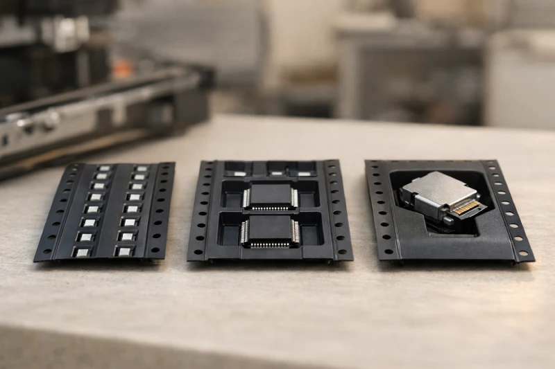
Not all components respond the same way to mechanical forces inside a pocket. Geometry, thickness, weight distribution, and lead exposure all influence how a component behaves during transportation and feeding.
For example, a symmetric ceramic capacitor tends to remain stable if lateral clearance is properly controlled. In contrast, a QFN package with exposed leads and uneven weight distribution may experience subtle rotation when subjected to feeder acceleration.
Pocket design must account for:
- Component thickness tolerance
- Lead protrusion risk
- Center of gravity
- Allowable lateral movement
A structure that is too tight can cause insertion stress or peeling interference. One that is too loose increases rotation and misalignment risk. Therefore, the application strategy should always be driven by component mechanics—not just tape width or standard availability.
What Is the Best Carrier Tape Approach for Passive Components (0402–1206)?
Passive components such as resistors and capacitors are small, lightweight, and typically symmetrical. However, their small size makes them highly sensitive to pocket dimensional accuracy.
For 0402 and 0603 components especially, even minimal lateral clearance variation can affect pick accuracy under high-speed feeding. The key considerations include:
- Tight pocket dimensional tolerance
- Stable cavity depth control
- Consistent pitch accuracy
- Smooth pocket wall surface
In high-volume environments, embossed structures are typically preferred due to their dimensional consistency and repeatability. However, simply choosing an embossed format is not enough—the pocket geometry must match component thickness variation to prevent bounce or tilt.
When passive components are used in high-speed SMT lines, pocket rigidity and feeding smoothness become even more critical to avoid placement deviation.
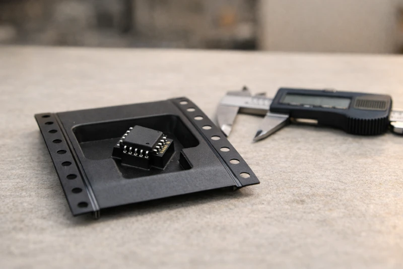
How Should ICs and Sensitive Devices Be Packed to Prevent ESD and Rotation?
ICs, QFN packages, BGAs, and other semiconductor devices introduce additional complexity beyond simple geometry control.
First, electrostatic discharge protection becomes essential. Packaging strategy must consider surface resistivity and charge dissipation performance to reduce ESD risk during transportation and handling.
Second, these devices often have asymmetric mass distribution. When feeder acceleration occurs, even slight lateral movement can result in rotational shift. For ICs, pocket depth and shoulder support design play a significant role in preventing tilt or flip.
Other critical factors include:
- Controlled cover tape peel force
- Stable pocket bottom support
- Adequate anti-static properties
- Minimal lead exposure contact
When rotation or orientation instability becomes visible in high-speed production, the issue often originates from insufficient pocket support rather than machine calibration.
When Is Custom Carrier Tape Necessary Instead of Standard Widths?
Standard 8mm, 12mm, and 16mm formats cover many common components. However, not every product fits comfortably within standard cavity assumptions.
Custom pocket design becomes necessary when:
- Component geometry is irregular
- Lead length exceeds typical cavity limits
- Height tolerance is wide
- Center of gravity is offset
- Special orientation control is required
Relying on standard pocket structures in such cases can result in chronic feeding instability. Even if short-term production appears acceptable, yield fluctuation may occur over time.
Custom application strategies allow pocket contour, depth, and clearance to be engineered specifically around the component’s mechanical behavior. This approach is especially important for newly developed devices or sensitive semiconductor packaging.
How Does Component Weight and Geometry Affect Pocket Design?
Component weight directly influences how much inertia is generated during feeder acceleration. Heavier devices generate higher dynamic force against pocket walls, increasing the risk of lateral shift.
Similarly, long or narrow components create torque when subjected to motion. If pocket support is not evenly distributed, micro-rotation may occur before pickup.
Engineering evaluation should consider:
- Center of gravity position
- Length-to-width ratio
- Thickness variation
- Dynamic force under feeder acceleration
Pocket depth must balance vertical stability with pick access. Too shallow increases pop-out risk; too deep may interfere with vacuum nozzle approach.
The most effective application strategy accounts for dynamic movement, not just static fit. Mechanical simulation or real feeding validation often reveals instability that dimensional inspection alone cannot detect.
What Packaging Strategy Works Best for High-Speed SMT Lines?
High-speed SMT lines introduce additional stress conditions. Acceleration, vibration, and peel dynamics amplify even minor structural inconsistencies.
At speeds exceeding 30,000 CPH, tolerance stacking becomes visible. Slight pitch variation, inconsistent pocket rigidity, or uneven material stiffness can cause cumulative feeding deviation.
To optimize performance in high-speed environments, consider:
- Material rigidity and dimensional stability
- Consistent pocket pitch accuracy
- Controlled cover tape peel strength
- Smooth feeding track interaction
A structure that performs adequately in mid-speed production may fail when line speed increases. Therefore, packaging evaluation should always match the intended SMT speed environment.
Carrier tape application strategy must align with production intensity—not just component size.
How to Evaluate Whether Your Current Carrier Tape Is Causing Yield Loss?
When yield issues appear, many teams first inspect feeder calibration or placement head alignment. However, packaging instability often remains overlooked.
Warning signs that indicate a carrier tape application issue include:
- Repeated component rotation
- Inconsistent pick angle
- Occasional mispick without feeder alarm
- Component bounce during feeding
- Yield fluctuation tied to specific reels
If instability occurs only at higher speeds but disappears during slow testing, dynamic pocket behavior is likely contributing.
A structured evaluation approach includes:
- Inspecting pocket clearance
- Reviewing component seating depth
- Measuring cover tape peel consistency
- Observing feeding motion under high-speed camera analysis
If structural mismatch is identified, adjusting the carrier tape strategy often provides more stable long-term improvement than machine recalibration alone.
Conclusion
Selecting the best carrier tape application strategy is not about choosing a category—it is about understanding component mechanics and production conditions.
Passive components, ICs, and custom geometries each require different structural considerations. High-speed SMT lines further increase tolerance sensitivity, making packaging design an active contributor to yield performance.
By evaluating component geometry, weight distribution, ESD sensitivity, and production speed, engineers can determine whether standard structures are sufficient or if a tailored approach is necessary.
A properly aligned carrier tape application supports stable feeding, consistent placement accuracy, and long-term manufacturing reliability.