Selecting carrier tape for IC chip packaging is often treated as a material decision. In reality, it is a dimensional and stability decision first. Many feeding failures, pick-and-place inconsistencies, and lead damage issues originate not from tape material, but from poor alignment between chip geometry, pocket tolerance, and line speed.
IC components are increasingly smaller, thinner, and more sensitive to mechanical and electrostatic stress. As SMT speeds increase, even minor clearance miscalculations can translate into rotation, flipping, or unstable pickup behavior. The correct selection process must therefore begin with structural matching, followed by tolerance control, ESD evaluation, and production line compatibility.
This guide outlines a practical engineering sequence to determine when standard formats are sufficient and when custom solutions become necessary — without over-specifying or increasing unnecessary cost.
What IC Packaging Parameters Must Be Confirmed Before Selecting Carrier Tape?
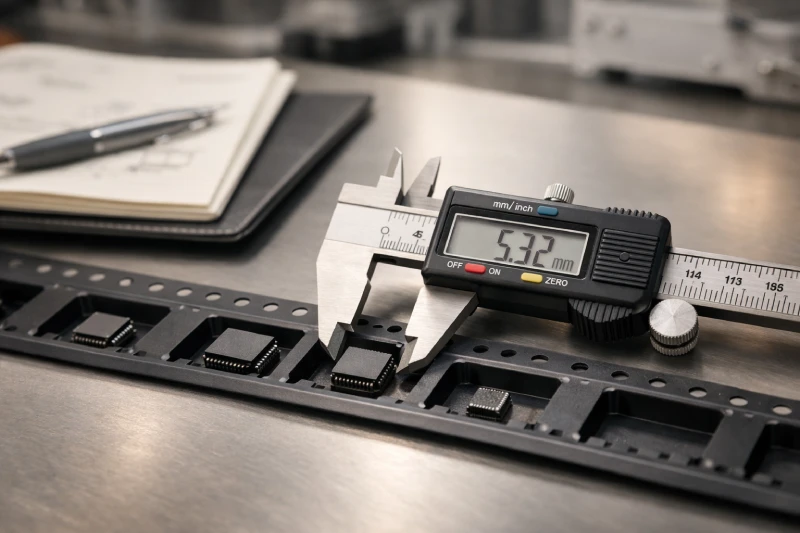
Before evaluating materials or formats, engineers must define the component’s physical and mechanical profile. Key parameters include overall length, width, and height, but also lead protrusion, body flatness, weight, and edge fragility.
For thin IC packages such as QFN or BGA, the vertical tolerance window becomes especially critical. A pocket that allows excessive vertical movement may cause floating during transport or vibration, while an overly tight cavity risks lead stress or corner damage.
Moisture Sensitivity Level (MSL) and surface sensitivity should also be reviewed. Highly sensitive components may require more controlled retention and stable sealing behavior.
Orientation requirements on reel must be confirmed early. Incorrect pocket orientation can create downstream programming and feeder alignment complications.
Without clearly defined input parameters, even high-quality embossed carrier tape may fail to deliver stable performance.
How Do Pocket Dimensions and Tolerance Control Affect IC Stability During SMT?
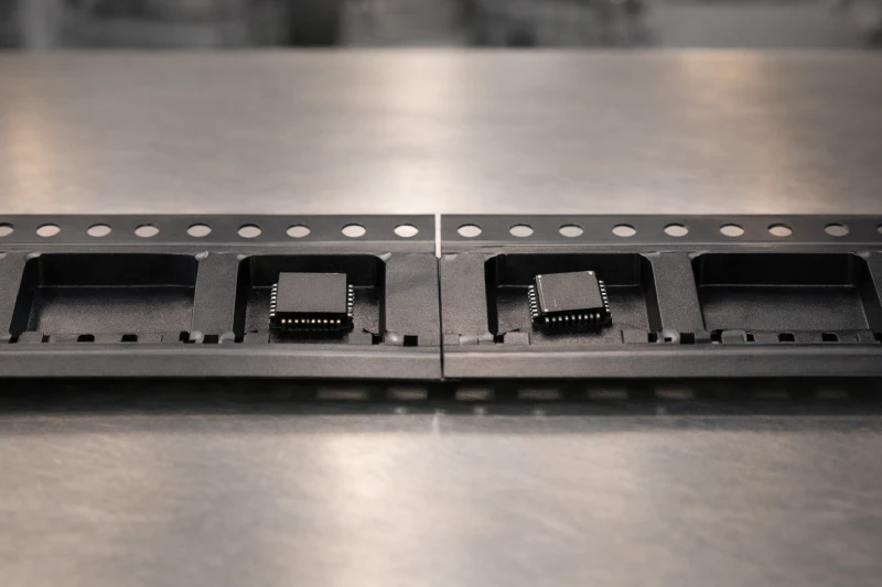
Pocket geometry directly determines component stability during feeding and pickup. The most common engineering mistake is allowing excessive lateral clearance. Even 0.1–0.2 mm additional gap can increase rotation probability at high feeder acceleration.
Three tolerance zones must be considered:
- Lateral clearance (X/Y movement)
- Vertical clearance (Z float)
- Pitch accuracy relative to sprocket hole positioning
At higher SMT speeds, feeder vibration and indexing forces amplify small dimensional inconsistencies. Components with marginal fit may remain stable during manual testing but fail under full production speed.
Tolerance stacking is another overlooked issue. Chip dimensional tolerance plus pocket forming tolerance plus tape elongation tolerance can accumulate, reducing effective control.
Proper pocket design ensures controlled movement without compression. Stability, not tightness, is the objective.
When dimensional requirements exceed common standards, custom pocket engineering becomes necessary to maintain consistent pickup rates.
When Is Anti-Static or Conductive Carrier Tape Necessary for IC Chips?
Not every IC requires conductive or anti-static material, but risk evaluation is essential. ESD sensitivity classifications such as HBM and CDM should guide material decisions.
Highly sensitive devices or those processed in low-humidity environments may benefit from dissipative or conductive structures to reduce electrostatic buildup. However, over-specification increases cost and may affect transparency or forming flexibility.
Environmental factors also matter. Production lines with controlled humidity and grounded feeders may reduce risk compared to uncontrolled storage or transport conditions.
The decision should balance component sensitivity, production environment, and handling stages. Anti-static structures are risk-management tools — not universal requirements.
How Does Material Selection (PS vs PET vs PC) Influence IC Packaging Performance?
Material selection influences forming precision, rigidity, and dimensional stability.
PS (polystyrene) offers good formability and cost efficiency for standard applications. PET provides improved mechanical strength and dimensional stability, especially in longer reel formats. PC offers higher rigidity and clarity, supporting more demanding structural designs.
However, material alone does not guarantee stability. A poorly designed pocket in premium material will underperform compared to a properly engineered cavity in standard material.
Temperature resistance, forming precision, and transportation duration should influence material choice. Long shipping routes or automated high-speed lines may justify stronger materials.
Selection should follow structural assessment, not precede it.
How to Prevent IC Rotation, Floating, or Lead Damage Inside the Pocket?
Rotation and lead damage are typically results of misbalanced pocket geometry rather than handling error.
Effective prevention strategies include:
- Controlled lateral support points
- Optimized vertical clearance
- Balanced cavity wall angles
- Proper cover tape sealing tension
Too much vertical gap allows bouncing during transport. Too little gap may cause friction or lead scraping. The ideal design restricts free rotation while avoiding mechanical compression.
Cover tape interaction is often overlooked. Excessive sealing pressure or mismatched peel strength can destabilize light components during feeding.
For long-distance export shipments, vibration resistance should also be evaluated. What works locally may fail after extended transit.
Mechanical stability must be validated under real feeder conditions, not only dimensional measurement.
How Do Feeding Speed and SMT Line Configuration Impact Carrier Tape Choice?
SMT line configuration significantly influences required tape rigidity and dimensional accuracy.
High-speed placement lines generate stronger indexing forces. Lightweight ICs in loosely fitted pockets are more prone to shifting under acceleration. In contrast, mid-speed lines may tolerate slightly larger clearance without immediate instability.
Feeder compatibility is another factor. Certain feeder types apply different pulling tension or cover tape peeling angles. These mechanical differences can influence tape deformation behavior.
Reel diameter and winding tension also affect pocket consistency over length. Larger reels may experience dimensional variation if material stability is insufficient.
Tape selection should align with the most demanding production line configuration, not average operating conditions.
When Should You Choose Custom Carrier Tape Instead of Standard Options?
Standard formats work effectively for many IC sizes within common dimensional ranges. However, custom engineering becomes necessary when:
- Component dimensions fall between standard cavity sizes
- Lead structures require asymmetric support
- Feeding failure rate exceeds acceptable threshold
- High-speed lines magnify minor rotation issues
Custom solutions allow pocket geometry to match exact chip structure rather than forcing compromise.
The decision should be based on long-term yield stability and risk reduction, not only initial tape cost. In high-volume IC packaging, small improvements in pickup consistency often justify custom development.
Conclusion
Choosing the right carrier tape for IC chip packaging is a structural engineering decision before it is a material decision. Accurate dimensional input, controlled tolerance design, feeder compatibility, and ESD evaluation must be assessed in sequence.
Pocket stability directly determines SMT consistency. Material selection enhances performance but cannot compensate for geometric mismatch. Feeding speed and production environment further define acceptable tolerance windows.
When standard solutions no longer ensure stable pickup and transport, custom pocket engineering provides a path to long-term reliability.
A disciplined selection process reduces rotation, lead damage, and feeding interruptions — ultimately improving yield across the entire SMT operation.