Introduction
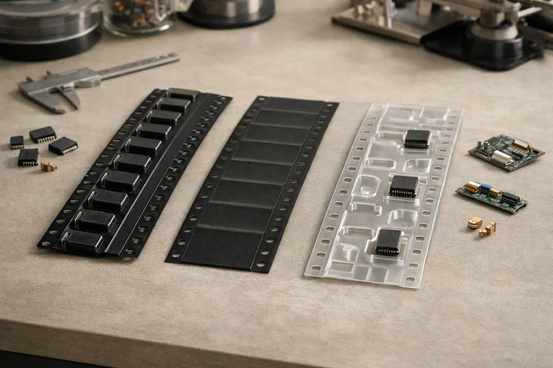
Carrier tape selection is often treated as a secondary detail in SMT projects. As long as a component fits the pocket and feeds without immediate issues, the tape is usually considered acceptable. The impact of that choice tends to appear later—during ramp-up, yield fluctuation, or when minor changes in component design or handling conditions start to expose weaknesses.
The challenge is that differences between embossed, anti-static, and custom carrier tapes are rarely obvious in early trials. A tape that runs smoothly at low volume can still introduce long-term risks, such as inconsistent feeding, part movement inside the pocket, or unnecessary sensitivity to electrostatic conditions. These effects are subtle enough that the carrier tape is often not questioned until other process variables have already been adjusted.
From an engineering standpoint, carrier tape type is a response to constraints rather than preference. Component geometry, dimensional tolerance, handling environment, and production scale all influence whether a standard embossed tape is sufficient, whether anti-static properties matter, or whether customization becomes unavoidable. Understanding where those boundaries lie is usually more valuable than comparing tape types in isolation.
Why Embossed Carrier Tape Becomes the Default for Most SMT Components
Embossed carrier tape is often selected by default not because it is universally optimal, but because it satisfies the most common mechanical requirements with the least number of assumptions. For the majority of SMT components, pocket-formed tape provides a predictable way to control part position, orientation, and retention during feeding.
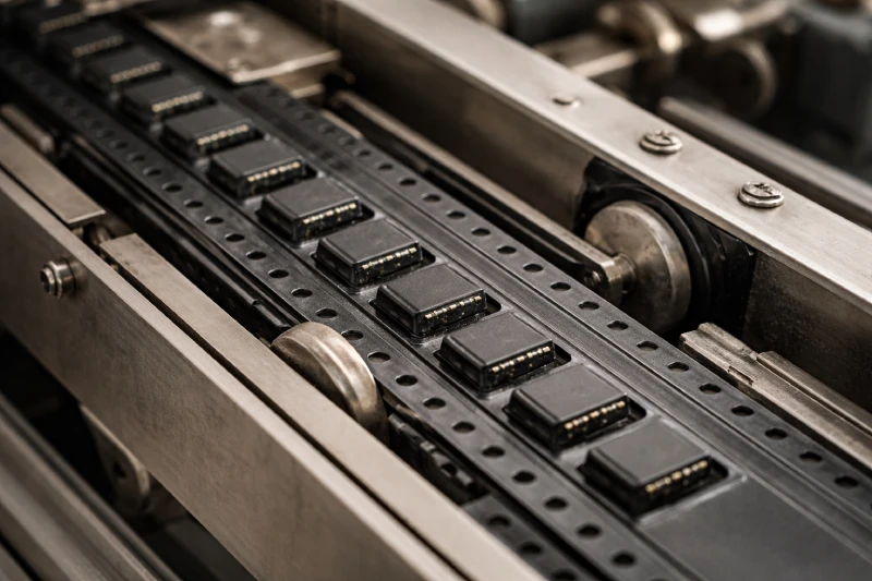
From a feeder perspective, embossed pockets offer physical constraints that flat or minimally formed tapes cannot. Pocket depth, wall angle, and pocket-to-pocket pitch create repeatability that aligns well with standard feeder designs. As long as component geometry is reasonably consistent, this structure reduces the likelihood of rotation, tilt, or part escape during indexing.
Another reason embossed tape becomes the baseline is tolerance absorption. Minor variations in component dimensions are often better handled by formed pockets than by relying solely on cover tape tension or friction. This is especially relevant when components come from multiple lots or suppliers, where nominal dimensions remain the same but real-world variation increases.
In early production stages, embossed carrier tape also minimizes setup complexity. Engineers can focus on placement accuracy, nozzle selection, and vision alignment without compensating for unstable part presentation. When feeding issues do occur, they are usually easier to diagnose because the mechanical behavior of embossed tape is well understood.
However, default does not mean universally correct. Embossed carrier tape works best when component geometry is stable, electrostatic sensitivity is manageable at the process level, and production volume does not amplify small inconsistencies. Understanding why it works in these conditions helps clarify when it may stop working—and when other carrier tape types should be considered.
At What Point Does Anti-Static Carrier Tape Actually Matter?
Anti-static carrier tape becomes relevant only when electrostatic risk is no longer theoretical within the process. In many SMT environments, ESD controls are already applied at the facility, equipment, and handling levels, which can make anti-static tape appear redundant during initial evaluation.
The need usually emerges when components remain exposed for longer periods—during storage, transportation between processes, or manual handling steps that fall outside tightly controlled zones. In these cases, carrier tape is no longer just a feeding medium but part of the ESD control chain. If charge accumulation or discharge events can occur before placement, tape material behavior starts to matter.
Component sensitivity also plays a role, but not in isolation. Highly sensitive devices do not automatically require anti-static carrier tape if upstream and downstream controls are effective. Conversely, moderately sensitive components may benefit from anti-static tape when process variability increases, such as mixed production lines or frequent changeovers.
Another indicator is inconsistency. If ESD-related defects appear intermittently and cannot be correlated with equipment or operator actions, packaging is often overlooked. Anti-static carrier tape is typically considered after other controls are validated, not as a first-line solution.
From an engineering standpoint, anti-static carrier tape addresses risk accumulation rather than immediate failure. Its value becomes clear when electrostatic exposure is cumulative, difficult to isolate, or influenced by logistics and handling rather than by the placement process itself.
When Standard Carrier Tape Designs Start to Fail
Standard carrier tape designs usually do not fail abruptly. Instead, they begin to show limitations through small, repeatable issues that are easy to attribute to other parts of the process. Misfeeds become more frequent, components shift slightly within the pocket, or feeder tuning requires more frequent adjustment to maintain the same yield.
One common signal is positional inconsistency. Parts may arrive at the pickup point with minor rotation or tilt that does not stop the line but increases vision correction time or placement variability. Over time, these small deviations accumulate into throughput loss or quality instability, even though no single failure mode appears critical on its own.
Another indicator is sensitivity to operating conditions. A setup that runs acceptably at lower speeds or smaller batch sizes may start to degrade as indexing speed increases or reels are used closer to their limits. Pocket retention that was “good enough” during trials may no longer be sufficient once vibration, acceleration, and continuous operation are introduced.
Standard designs also tend to struggle when component dimensions sit near tolerance limits. As dimensional variation increases across lots, pocket fit can shift from controlled to marginal without any change to the nominal specification. In these cases, engineers often compensate by adjusting cover tape tension or feeder settings, which can mask the underlying mismatch rather than resolve it.
Recognizing these patterns early helps distinguish between process noise and packaging constraints. When repeated adjustments fail to stabilize feeding behavior, the issue is often not the feeder or the placement program, but the limits of a standard carrier tape design being reached.
What Usually Triggers the Need for Custom Carrier Tape
Custom carrier tape is rarely chosen because a component is “special.” In most cases, it becomes necessary when standard pocket designs can no longer control part behavior within acceptable margins. The trigger is usually functional, not cosmetic or specification-driven.
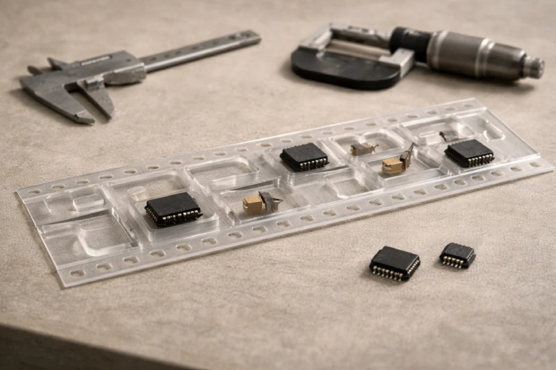
One common driver is geometry that defeats generic pocket assumptions. Components with asymmetric shapes, uneven mass distribution, or critical orientation requirements can behave unpredictably in standard pockets, even if nominal dimensions appear compatible. In these cases, the issue is not fit, but control—how consistently the part settles and presents itself at pickup.
Another trigger is process sensitivity. When placement accuracy, coplanarity, or lead integrity becomes more critical, small variations in part position inside the pocket start to matter. Custom pocket features—depth profiling, localized support, or controlled clearance—are often introduced to stabilize those variables rather than to accommodate size alone.
Automation constraints also play a role. High-speed feeders, non-standard indexing behavior, or specific nozzle interactions can expose weaknesses that were not visible at lower throughput. What runs acceptably in a flexible setup may fail once the process is optimized for speed and repeatability.
In practice, custom carrier tape is usually a response to accumulated friction: repeated feeder tuning, rising scrap rates, or growing dependence on operator intervention. When effort increases without a corresponding improvement in stability, customization becomes a way to reset the mechanical relationship between component, tape, and feeder—rather than an upgrade for its own sake.
How Component Geometry Influences Carrier Tape Choice More Than Material
Carrier tape decisions are often framed around material properties, but in practice, component geometry usually has a stronger influence on whether a tape performs reliably. Shape, mass distribution, and tolerance stack-up determine how a component settles into a pocket and how consistently it remains positioned through indexing and feeding.
Components with simple, symmetric outlines tend to tolerate a wider range of pocket designs. As long as clearance is controlled and depth is appropriate, material differences have limited impact on mechanical stability. Problems start to appear when geometry introduces imbalance—uneven thickness, offset centers of gravity, or features that contact the pocket walls unevenly.
Tolerance interaction is another overlooked factor. Even when nominal dimensions are well defined, real-world variation can shift how a component interfaces with the pocket. A pocket design that works at the center of the tolerance range may become marginal at the extremes, leading to intermittent rotation or lift that is difficult to diagnose.
In these cases, changing tape material rarely resolves the issue. Adjustments to pocket geometry—wall angle, support points, or clearance distribution—are usually more effective than switching between standard and anti-static plastics. Geometry governs mechanical behavior first; material properties modify it only at the margins.
For engineers, this distinction matters because it helps prioritize investigation. When feeding or placement instability appears, understanding how the component physically interacts with the pocket often provides clearer answers than focusing on tape material alone.
How Carrier Tape Selection Impacts Feeder Performance Over Time
Feeder performance is often evaluated during setup or initial production, but the influence of carrier tape selection becomes more apparent over extended runs. A tape that feeds reliably at the beginning of a shift may introduce variability as operating time, reel usage, and mechanical wear increase.
One factor is consistency. Small variations in pocket geometry, tape stiffness, or cover tape interaction can lead to gradual changes in how parts present themselves at the pickup point. Over time, feeders may require more frequent adjustment to maintain the same level of accuracy, even though no single parameter appears to be out of specification.
Wear amplification is another consideration. Repeated indexing and tension cycles can magnify minor mismatches between tape design and feeder mechanics. What appears as normal wear in isolation may translate into increased misfeeds or pickup retries when combined with marginal pocket retention or inconsistent tape behavior.
Production scale also matters. As volume increases, the cost of small inefficiencies becomes more visible. A slight increase in feeder stoppages or placement corrections may be acceptable in short runs but becomes disruptive in continuous operation. In these cases, carrier tape selection influences not just feeding reliability, but the amount of ongoing effort required to keep the line stable.
Evaluating carrier tape performance over time shifts the decision from “does it run” to “how much intervention does it require.” That distinction often determines whether a tape remains viable as production demands grow.
How Engineers Typically Revisit Carrier Tape Decisions During Scale-Up
Carrier tape decisions are rarely revisited when a process is stable, but scale-up has a way of exposing assumptions that were never formally validated. As production volume increases, the margin for variation narrows, and packaging choices that were once “good enough” begin to demand closer scrutiny.
One common trigger is a change in context rather than design. Higher throughput, longer continuous runs, or a shift in supplier mix can alter how components behave inside the same tape specification. What worked during pilot builds may no longer tolerate accumulated variation at scale.
Another factor is organizational handoff. When a project moves from engineering validation to sustained production, responsibility shifts toward efficiency and repeatability. At that stage, recurring feeder adjustments or operator-dependent fixes become visible costs, prompting a re-evaluation of whether the carrier tape is supporting the process or quietly consuming resources.
Experienced teams often revisit carrier tape specifications not after a major failure, but when incremental effort increases without a clear root cause. Scale-up makes these patterns harder to ignore. Reassessing tape type at this point is less about optimization and more about restoring alignment between component behavior, equipment capability, and production expectations.