Introduction
In automated SMT and semiconductor assembly, carrier tape is rarely discussed unless something goes wrong. Engineers typically encounter it not as a standalone product, but as part of a larger packaging and feeding system that must work reliably at scale. When carrier tape selection or design is inappropriate, the consequences tend to surface downstream—mis-picks, component damage, feeder interruptions, or unstable placement accuracy.
This article does not attempt to redefine carrier tape or compare specific product types. Instead, it focuses on the practical role carrier tape plays in component handling, protection, and process stability, and on how engineers determine when it is required and how it should function within a given application. By examining carrier tape from a system and decision-making perspective, the goal is to clarify why its design and use matter long before components reach the pick-and-place stage.
The Role of Carrier Tape in Component Handling and Protection
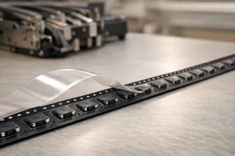
In high-volume electronic assembly, most component-related risks occur before placement rather than during it. Carrier tape addresses this by providing a controlled physical environment that stabilizes components throughout transport, storage, and automated feeding. Its primary role is not simply containment, but risk reduction across multiple handling stages.
Without a defined carrier structure, components are exposed to orientation shifts, mechanical contact, and cumulative micro-damage caused by vibration or manual handling. These issues may not be immediately visible, but they directly affect downstream process stability. Carrier tape minimizes such variability by fixing each component in a consistent position and orientation, allowing feeders and pick-and-place systems to operate within predictable mechanical tolerances.
Protection is also closely tied to repeatability. A well-matched carrier tape maintains consistent pocket geometry and retention force, reducing movement during acceleration and deceleration inside feeders. This consistency lowers the likelihood of partial lifts, component tilt, or pocket drag, all of which can contribute to mis-picks or intermittent placement errors.
From an engineering perspective, carrier tape should be viewed as a passive but critical control layer—one that absorbs handling uncertainty so that placement accuracy and yield are not compromised later in the process.
Carrier Tape as Part of the Tape-and-Reel Packaging System
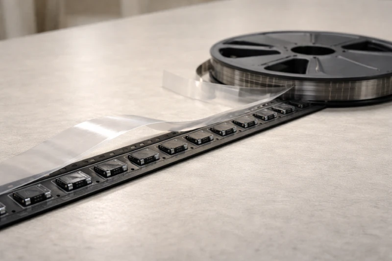
Carrier tape does not operate in isolation; its performance is inseparable from the tape-and-reel system as a whole. Within this system, carrier tape defines the mechanical baseline—pocket position, pitch accuracy, and component orientation—on which other elements depend. When these fundamentals are unstable, downstream adjustments rarely compensate effectively.
From an engineering standpoint, carrier tape is responsible for presenting components in a repeatable, machine-readable format. Cover tape manages retention and release behavior, while the reel governs tension and transport. Each element has a distinct role, but carrier tape establishes the reference geometry that feeders and indexing mechanisms rely on. If pocket alignment, sprocket hole accuracy, or pitch consistency deviate, the system’s weakest point is exposed during high-speed operation.
This interdependence explains why carrier tape issues often appear as feeder or placement problems rather than packaging faults. Engineers troubleshooting tape-and-reel performance therefore need to assess carrier tape not as a material choice, but as a structural interface between component design and automated assembly equipment.
Situations Where Carrier Tape Is Required Versus Optional
The need for carrier tape is not universal across all electronic components or production scenarios. Its necessity is largely determined by the level of automation, production volume, and component sensitivity rather than by industry convention. In fully automated SMT lines, carrier tape is typically required because feeders and pick-and-place systems rely on consistent indexing and orientation control to maintain throughput and accuracy.
In contrast, low-volume or manual assembly environments may tolerate alternative packaging methods when component geometry and handling risk are minimal. Bulk packaging or tray-based formats can be sufficient if placement speed, repeatability, and long-term storage stability are not critical constraints. However, as automation increases, these alternatives quickly reveal limitations in alignment control and handling consistency.
Carrier tape becomes functionally necessary when components must be fed at high speed, protected from cumulative handling damage, or maintained in a fixed orientation throughout transport and storage. From a decision-making standpoint, the question is less about whether carrier tape is “standard,” and more about whether the process can tolerate variability. When variability is unacceptable, carrier tape shifts from an optional packaging choice to a structural requirement.
How Component Geometry and Sensitivity Affect Carrier Tape Design
Component characteristics are the primary drivers of carrier tape design, even though this relationship is often underestimated during early packaging decisions. Geometry, mass distribution, and surface features all influence how a component interacts with the pocket that holds it. When these factors are mismatched, the resulting issues usually appear during feeding rather than at the packaging stage.
Components with irregular outlines, asymmetric profiles, or exposed leads require pocket geometries that control both lateral movement and rotational freedom. If the pocket does not adequately constrain these degrees of freedom, components may shift during transport or acceleration inside feeders, increasing the risk of mis-picks or orientation errors. Conversely, overly restrictive pockets can introduce friction or extraction resistance that disrupts consistent pickup.
Sensitivity further complicates the design balance. Fragile components, fine-pitch devices, or parts with electrostatic vulnerability impose additional constraints on pocket depth, support points, and material behavior. In these cases, the carrier tape must stabilize the component without introducing mechanical stress or surface contact that could degrade reliability.
For engineers, evaluating carrier tape suitability therefore begins with understanding component behavior under motion—not with tape specifications. The more complex or sensitive the component, the more tightly carrier tape design and application become coupled.
Impact of Carrier Tape on Pick-and-Place Stability and Yield
Carrier tape influences pick-and-place performance in ways that are often indirect but measurable over time. While placement accuracy is typically attributed to machine calibration or nozzle condition, inconsistencies in carrier tape frequently introduce variability that machines are not designed to correct dynamically.
During high-speed operation, even minor pocket misalignment or inconsistent retention can affect how a component presents itself at the pickup point. Components that shift, tilt, or sit at inconsistent heights force the pick head to compensate within limited tolerance windows. When these compensations fail, the result is partial pickup, dropped components, or intermittent mis-picks that may not trigger immediate alarms but gradually impact yield.
Carrier tape also affects feeder stability. Irregular tape tracking, pocket drag, or inconsistent release behavior can cause brief feeder interruptions or indexing errors, especially in dense or high-mix production environments. These issues accumulate as downtime, rework, or scrap rather than as isolated failures.
From an engineering perspective, stable pick-and-place performance depends on reducing variability before components reach the machine. Carrier tape plays a quiet but decisive role in maintaining that stability across long production runs.
Key Factors Engineers Consider When Evaluating Carrier Tape Suitability
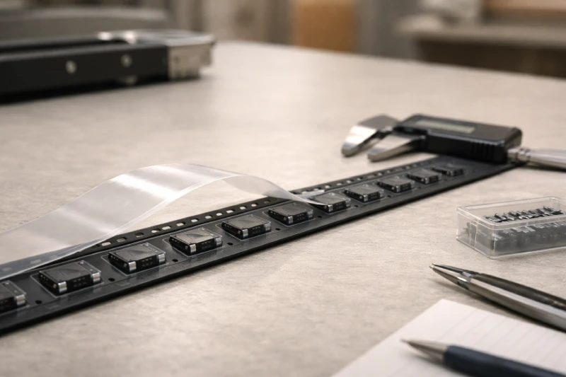
Evaluating carrier tape suitability is less about checking individual specifications and more about understanding how the tape behaves within a specific process. Engineers typically assess suitability by observing whether the carrier tape reduces variability rather than introducing new constraints into the system.
One key factor is dimensional consistency over time. Pocket geometry, pitch accuracy, and sprocket alignment must remain stable across long runs and multiple reels. Variations that appear minor during inspection can amplify under continuous feeder motion. Another consideration is retention balance—components should remain secure during transport and indexing, yet release cleanly and predictably at pickup without excessive force.
Process compatibility is equally important. Carrier tape must interact reliably with existing feeder designs, cover tape behavior, and reel tension settings. A tape that performs well in isolation may still create instability when integrated into a specific line configuration. Engineers therefore often evaluate carrier tape by monitoring feeder smoothness, mis-pick frequency, and operator intervention rather than by relying solely on datasheets.
Ultimately, no carrier tape is universally suitable. Effective evaluation recognizes trade-offs and prioritizes process stability, repeatability, and yield over nominal specifications.
Common Carrier Tape Applications Across SMT and Semiconductor Manufacturing
Carrier tape is applied across a wide range of SMT and semiconductor manufacturing stages, but its role varies depending on process requirements and integration depth. In high-volume SMT assembly, it supports continuous, high-speed feeding where consistency and uptime are critical. In semiconductor and advanced packaging environments, carrier tape is often used earlier in the supply chain, where component protection and orientation control must be maintained over longer handling and storage cycles.
Different manufacturing contexts place different emphasis on carrier tape performance. Some prioritize feeding stability and placement accuracy, while others focus on handling protection, contamination control, or electrostatic risk management. These differences explain why carrier tape solutions tend to be application-specific rather than interchangeable across processes.
Understanding how carrier tape functions within each manufacturing context allows engineers and decision-makers to align packaging choices with actual process needs, rather than relying on generalized assumptions about standard packaging formats.